# Overview

This document gives an overview of the Ethernal Blade blockchain.

## Introduction

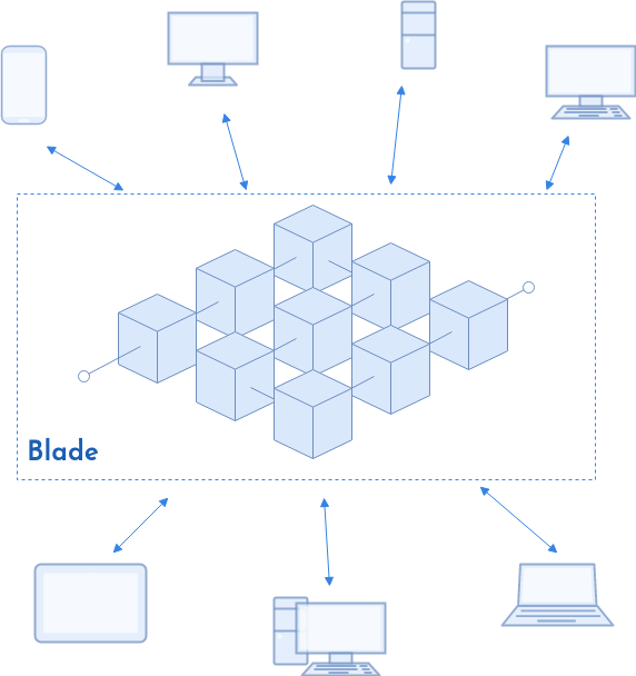
Blade is a cutting-edge blockchain platform designed with a clear focus on enterprise needs. It is the ultimate choice for businesses aiming to harness the power of blockchain technology due to its exceptional speed and precision. It streamlines complex data management, optimizes supply chain, and secures transactions seamlessly.

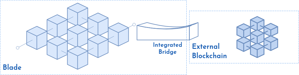
<figure><img src="https://3820615377-files.gitbook.io/~/files/v0/b/gitbook-x-prod.appspot.com/o/spaces%2F4nX3GBMyBbMsZe2u4kJt%2Fuploads%2Fgit-blob-d418ea84ed6d36194827d97d008497627893fb95%2Fsystem_architecture-v4.drawio.png?alt=media" alt=""><figcaption><p>Figure 1 - Blade Blockchain</p></figcaption></figure>

## Main Features

The main features of Blade Blockchain include:

* Rapid transaction processing and low gas consumption (Table 1).

#### Table 1 - Transaction processing and gas consumption

| Scenario                        | Transactions per second |
| ------------------------------- | ----------------------- |
| Multiple native token transfers | 8404                    |
| Multiple ERC20 transfers        | 4831                    |

* Highly configurable and customizable interfaces and system setup.
* Ethereum Virtual Machine (EVM) compatibility.
* Native Bridge integration right out of the box - General Message Passing feature (Figure 2).
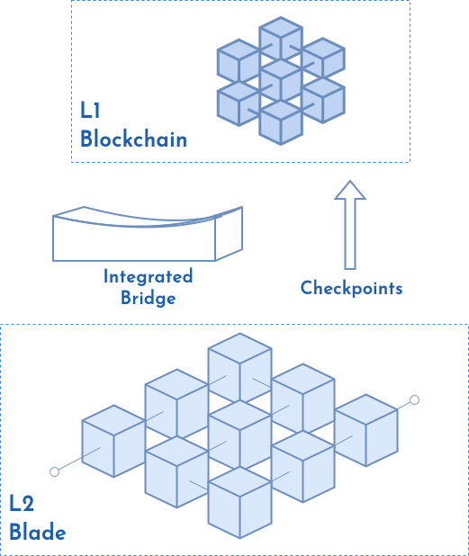
* L1 solution configurable (Figure 2).

<figure><img src="https://3820615377-files.gitbook.io/~/files/v0/b/gitbook-x-prod.appspot.com/o/spaces%2F4nX3GBMyBbMsZe2u4kJt%2Fuploads%2Fgit-blob-d8ca16d11bfb722ff895510071973adb44c9fb50%2Fsystem_architecture-L1%26IntegratedBridge.drawio.png?alt=media" alt=""><figcaption><p>Figure 2 - Blade as L1 and Integrated (General Message Passing) bridge</p></figcaption></figure>

* L2, L3,... solution configurable (Figure 3).

<figure><img src="https://3820615377-files.gitbook.io/~/files/v0/b/gitbook-x-prod.appspot.com/o/spaces%2F4nX3GBMyBbMsZe2u4kJt%2Fuploads%2Fgit-blob-71c67a1c0e2142384c9bcaa0d4b9c6c74df15b81%2Fsystem_architecture-L2.drawio.png?alt=media" alt="" width="391"><figcaption><p>Figure 3 - Blade as L2 Layer</p></figcaption></figure>

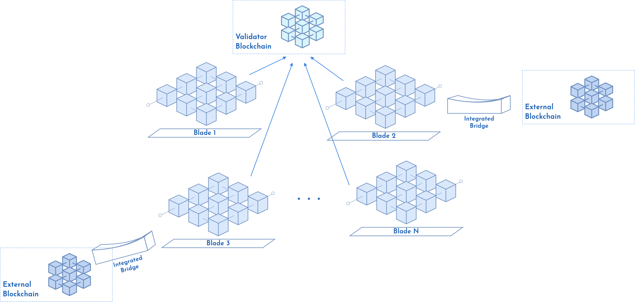
* Capable of constructing a hub of interconnected blockchains with shared validators (Figure 4).

<figure><img src="https://3820615377-files.gitbook.io/~/files/v0/b/gitbook-x-prod.appspot.com/o/spaces%2F4nX3GBMyBbMsZe2u4kJt%2Fuploads%2Fgit-blob-1aeae93a437e4cd66304af663cb6a0e9bdd16ce5%2Fsystem_architecture-Hub.drawio.png?alt=media" alt=""><figcaption><p>Figure 4 - Hub of Blockchains</p></figcaption></figure>

* Pluggable consensus mechanism.
* Configurable Stake and Reward tokens.
* User-Friendly user experience.
* Block Explorer.
* Free transactions, Account Abstraction, Governance, etc.
* Robust security measures to safeguard user data and transactions, incorporating advanced encryption techniques.
* Full compliance and auditing.


# High-level Architecture

This section gives an overview of the Ethernal Blade blockchain high-level architecture.

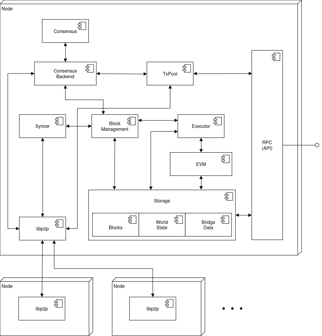
To better understand the Blade system, the high-level architecture diagram of components is illustrated below. A node in the diagram is any instance of Blade software connected to other computers running Blade software, forming a network. We also refer to this node as the Blade client or client for short.

<figure><img src="https://3820615377-files.gitbook.io/~/files/v0/b/gitbook-x-prod.appspot.com/o/spaces%2F4nX3GBMyBbMsZe2u4kJt%2Fuploads%2Fgit-blob-bacf76b94026cdc482ffbe4130e615229485afa6%2Fsystem_architecture-high-level%20arch%20with%20syncer.drawio(3).png?alt=media" alt=""><figcaption><p>High-level Architecture Component Diagram</p></figcaption></figure>

The client exposes predefined RPC methods through an API (JSON-RPC within the `RPC` component). Among other things, this enables the sending of transactions to the blockchain and the reading of current blockchain data.

Sent transactions are submitted to the transaction pool (represented by `TxPool` component). For reading a block from the blockchain, a transaction from a block, or the current state of an account, a request is submitted to the `Storage` component. The `Storage` component is a general abstraction for different types of storage holding various data like the blockchain itself, the world state, bridge data, etc.

The transaction pool prioritizes received transactions, usually by giving an advantage to transactions with higher gas prices, but the applied criteria may differ. Each received transaction from the transaction pool is sent to the rest of the nodes/peers in peer-to-peer network using the `libp2p` communication component. This component uses gossip mechanism (gossipsub) to spread received messages through the network.

There are two types of Blade clients: full nodes and validators. Full nodes store the entire blockchain and they do not participate in block validation. Validators, as their name suggests, participate in block validation.

If a client node is in the role of a validator, it takes part in the block creation process, and the consensus mechanism is an integral part of its operational behavior. The consensus mechanism, which is essentially an algorithm using state transitions based on the received confirmations, helps validators come to an agreement regarding the validity of a proposed block. The `Consensus` component (the algorithm) is supported by the `Consensus Backend` component.

As the algorithm assumes that only one validator from all consensus participants/validators is a block proposer, the `Consensus Backend` also holds the logic to determine whether the validator is a proposer or not. For example, when the consensus algorithm starts, it checks the proposer status of the validator, and if the status is true, it calls the `Block Management` component, which takes transactions from the `TxPool` to form a proposed block. The consensus relies on a number of messages (such as PREPARE, COMMIT, etc.) during different stages of the block creation process. These messages are created by the `Consensus Backend` as well. As all validators equally participate in the consensus, the messages have to be distributed to all of them. The communication layer of the `Consensus Backend` ensures that all messages are sent to all peers through `libp2p`. Messages work in pub/sub manner meaning that only subscribed nodes receive messages for the given topic.

Once all messages are exchanged through different consensus phases, and assuming that consensus is reached (meaning that the proposed block is valid and ready to be added to the blockchain), the next step is to apply all block transactions and add the block.

The `Block Management` component takes the block and sends each transaction for execution. The `Executor` component determines whether it is a smart contract call or an external owned account (EOA) balance change, and applies them accordingly. In the case of a smart contract, the contract is retrieved from storage and sent to the `EVM` (Ethereum Virtual Machine) for execution. Consequently, the `World State` is updated by the `EVM`, adjusting the balance of the contract account and its storage. For EOAs, the `World State` is directly updated by adjusting the balance of the account. After all transactions are executed and the `World State` is updated, the block's header is also updated with the latest `World State` hash and the block is appended to the blockchain (saved in `Blocks` storage). The block is also sent to all peers using `Syncer` component.

When a node is a validator, both the `Consensus` and `Syncer` components are up and running. On the other hand, for full nodes, only the `Syncer` is running. As mentioned, the `Consensus` serves to create blocks, while the `Syncer`'s purpose is to synchronize the node's blocks with the rest of the network. The `Syncer` connects to another node and fetches blockchain differences (i.e. blocks) by using an internal protocol that compares the indices of the latest blocks on the nodes. After a newer block is received, the `Syncer` sends it to `Block Management`, which in turn checks if the block already exists in the chain, because there is a chance that the `Consensus` created it. Otherwise, the newer block is applied by `Block Management` (the block is validated, its transactions are executed, and the updated block is appended to the blockchain). At the same time, currently running consensus execution is halted, as it is stale.


# Considerations

This section is dedicated to outlining a comprehensive strategy for ensuring data security within the Blade chain for multiple cloud providers. The primary objective is to implement measures facilitating the smooth deployment of Blade across different vendors, thereby mitigating the risk of vendor lock-in. The chapter aims to articulate the necessary steps for adopting a cloud-first Secure by Design approach.

As the focus is on **confidentiality**, the discussion delves into three key aspects of encryption within Blade data protection framework:

1. Data at rest encryption
2. Data in transit encryption
3. Data in use encryption

It is essential to discern the primary focus of each encryption aspect across different scenarios. To achieve this, a **risk-based methodology** is presented, along with tailored response strategies for identified threats.

To elaborate further, the chapter addresses the following specific areas:

* Encryption protocols relevant to Infrastructure as a Service (IaaS) and general compute environments (e.g., Azure Virtual Machine, AWS EC2, and GCP Compute Engine), including virtual disks.
* Implementation of the gRPC framework to ensure secure communication, with a particular emphasis on encryption in transit.
* Encryption measures for RPC via HTTPS requests originating from the computational environment.
* Secure management of keys that involves implementing robust protocols, strict access controls, and secure storage solutions such as Key Vaults or Hardware Security Modules (HSMs).

## Preconditions and Inputs

To ensure data protection of Blade, it is necessary to execute the following steps:

1. Data classification / Inventory
2. Regulations, requirements, and industry best practices
3. Design reviews and threat modeling
4. Establishing Data Protection processes

**Data classification** tags data according to its type, sensitivity, and value to the organization if altered, stolen, or destroyed. It helps an organization understand the value of its data, determine whether the data is at risk, and implement controls to mitigate risks. As a first step, it’s necessary to define different data categories and describe them. Some sensitive data like keys, secrets, and other authentication identifiers are clearly sensitive data, but when it comes to business-critical data and PII (personally identifiable information), the data classification needs special focus and attention.

**Requirements** are sourced from applicable laws, executive orders, directives, regulations, policies, standards, procedures, or mission/business needs to ensure the confidentiality, integrity, and availability of information that is being processed, stored, or transmitted. ([definition](http://csrc.nist.gov/glossary/term/security_requirement)). However, it is of utmost importance to perform proper **threat modeling** to elicit additional requirements in the context of the software design that will lead to proper design reviews ensuring Secure by Design is a driving principle from initial stages of software development.

**Data protection processes** are methods and practices to safeguard personal data from unauthorized or unlawful access, use, disclosure, alteration, or destruction. The processes need to be established to ensure software vendor’s alignment with regulations and laws.


# Data Classification

The following table presents an overview of sensitive data types handled by the system. P1 is designated for highly sensitive data, P2 for sensitive data, and P3 for all other business critical data. This classification system helps prioritize the protection of different types of data based on their sensitivity and criticality.

Understanding and categorizing the types of sensitive data is crucial for maintaining data security and compliance with relevant regulations. By clearly defining the nature of the data handled by the system, appropriate safeguards and controls to protect the confidentiality and integrity of this information can be established. Furthermore, a privacy policy can be developed.

<table><thead><tr><th width="119">Category</th><th width="140">Subcategory</th><th>Description</th><th data-hidden></th></tr></thead><tbody><tr><td>P1</td><td>Login information</td><td>Credentials used to access a system or platform. If revealed, such data can lead to unauthorized access, data breaches, and potential system compromise.</td><td></td></tr><tr><td>P1</td><td>Financial Data</td><td>Public wallet addresses and the associated transactional data. If revealed, such data can potentially expose sensitive financial information.</td><td></td></tr><tr><td>P2</td><td>Tracking</td><td>IP address, browser fingerprint and session ids. However, these data used within the system cannot be directly linked to some individual. If revealed, there is the risk of malicious attacks targeting an individual's device or network in general. Also, it may lead to targeted identity theft efforts.</td><td></td></tr><tr><td>P2</td><td>Social</td><td>Connections, usual exchanges between accounts and similar activities among public wallet addresses and their analysis. If revealed, such data may lead to exploitation of personal connections, and potential manipulation or misuse of individuals' relationships and activities</td><td></td></tr></tbody></table>

The system **does NOT** handle highly sensitive data pertaining to race, ethnicity, political affiliations, biometrics/genetics, health conditions, sexual orientation, criminal offenses, private communications, personal diaries, precise location data, or national unique identifiers.


# Risk Based Methodology

From an attacker perspective, it is important to understand that data is typically the end goal of the attacker to deliver the impact of the attack. Per MITRE ATT\&CK framework (see [here](https://attack.mitre.org/matrices/enterprise/)), exfiltration (see [here](https://attack.mitre.org/tactics/TA0010/)) deserved a separate category. However, turning to the STRIDE framework and focusing on Information Disclosure, we can focus on the virtual machines hosting App chain nodes and the communication among these nodes to identify and narrow down the threats requiring mitigation during the operation of Blade.

![Threats to information disclosure](https://3820615377-files.gitbook.io/~/files/v0/b/gitbook-x-prod.appspot.com/o/spaces%2F4nX3GBMyBbMsZe2u4kJt%2Fuploads%2Fgit-blob-d8704282d56cedce962731e912a2d88dc6c0ec0c%2F1.png?alt=media)

## **Threat 1** - Sensitive data in the VM can be disclosed if the OS or the file system in the virtual machine is not encrypted

This threat is mitigated through common mitigation strategies, which involve encrypting disks utilized by virtual machines. These strategies leverage configurations supported by all major cloud vendors. Typically, they rely on standard mechanisms built for different operating system versions – BitLocker for Windows OS family and DM-Crypt technology for UNIX based OS family.

It is important to ensure the encryption keys are stored properly and careful consideration regarding the entity responsible for generating these keys is crucial. More about proper key management can be found in the Key Vaults section of this document.

**The recommendation:** Today, full disk encryption is expected practice to ensure **data at rest** encryption and it should be done in almost all cases when using public cloud resources.

\[More information – Azure]: [Sensitive Data - Microsoft Threat Modeling Tool - Azure | Microsoft Learn](https://learn.microsoft.com/en-gb/azure/security/develop/threat-modeling-tool-sensitive-data#disk-vm)

\[Configuration – Azure]: [Azure Disk Encryption scenarios on Windows VMs](https://learn.microsoft.com/en-us/azure/virtual-machines/windows/disk-encryption-windows)

\[Configuration – AWS]: [Encryption best practices](https://docs.aws.amazon.com/prescriptive-guidance/latest/encryption-best-practices/services-best-practices.html) and specifically, for [VMs.](https://docs.aws.amazon.com/prescriptive-guidance/latest/encryption-best-practices/ec2-ebs.html)

\[Configuration – GCP]: [Encrypt disks with customer-supplied encryption keys](https://cloud.google.com/compute/docs/disks/customer-supplied-encryption)

**Blade mitigation:** In the deployment phase of the Blade chain, the configuration for instantiating VMs that host Blade nodes is tailored based on the selected cloud provider. This configuration is specifically designed to activate disk encryption. The combined effect of this applied configuration and the cloud provider's capability to encrypt disks ensures comprehensive protection for sensitive data within Blade.

## **Threat 2 –** Sensitive data can be accessed without customers consent by a vulnerability in CSP platform or it could include a malicious system operator

The concept of confidential computing protects the data from cloud system software vulnerabilities preventing even other tenants from exploiting other tenants' data, cloud operators, and with the concepts of enclaves, it protects the data from software operators as well. It achieves these goals by relying on TEE (Trusted Execution Environment) supported by new hardware technologies where processors separate different execution areas segregating the data and application code from the OS context. The encryption keys are stored within the processor chips themselves. We may say that this mitigation strategy relies on **data at rest and data in use** encryption.

All sensitive workloads should explore the option of using TEE virtual machines for elevated data protection.

Trusted computing also has a use case for enterprise blockchains as it enables preserving confidentiality of blockchain data (see [here](https://www.intel.com/content/dam/www/public/us/en/documents/solution-briefs/intro-to-confidential-computing-solution-brief.pdf)) by ensuring only authorized parties can see the data and transaction happening on the permissioned blockchain network.

**The recommendation:** If the target application works with sensitive data or has high-risk profile data and is being considered for public cloud deployment, trusted VMs and in general, confidential computing services fall under a **must requirement** category.

\[More information – Azure]: [Confidential Computing – Protect Data In Use | Microsoft Azure](https://azure.microsoft.com/en-us/solutions/confidential-compute)

\[Configuration – Azure VM]: [About Azure confidential VMs](https://learn.microsoft.com/en-us/azure/confidential-computing/confidential-vm-overview)

\[More information – AWS]: [Confidential computing: an AWS perspective](https://aws.amazon.com/blogs/security/confidential-computing-an-aws-perspective/)

\[Configuration – AWS VMs (EC2)]: Today, memory encryption is enabled by default on all [Graviton2-based instances](https://aws.amazon.com/ec2/graviton/) (T4g, M6g, C6g, C6gn, R6g, X2g), and Intel-based [M6i instances](https://aws.amazon.com/blogs/aws/new-amazon-ec2-m6i-instances-powered-by-the-latest-generation-intel-xeon-scalable-processors/), which have Total Memory Encryption (TME).

\[More information – GCP]: [Introducing Google Cloud Confidential Computing](https://cloud.google.com/blog/products/identity-security/introducing-google-cloud-confidential-computing-with-confidential-vms)

\[Configuration – GCP]: From the link above: all GCP workloads you run in VMs today can run as a Confidential VM. One checkbox - it’s that simple.

**Blade mitigation:** During the deployment phase of the Blade chain, Trusted Execution Environment (TEE) virtual machines serve as the foundational hosts for the nodes. This strategic choice reflects a deliberate architectural decision aimed at providing the security and reliability of Blade infrastructure. By leveraging TEE virtual machines, Blade ensures a heightened level of trustworthiness in its node hosting environment. TEE technology provides a secure execution environment that safeguards critical operations and data within isolated enclaves, protecting against unauthorized access and tampering attempts.

## Threat 3 - Sensitive data can be sniffed through unencrypted traffic

TLS is a protocol that encrypts data in transit between App chain nodes. This encryption ensures that sensitive information is protected from interception and unauthorized access. To implement TLS, one must rely on a TLS certificate from a reliable certificate authority (CA) which usually comes in the form of X509v3 standard certificate.

**The recommendation:** It is important to understand compliance needs as well as the risk profile of the software to understand where TLS traffic should be terminated, and this decision is usually a balance among security, management complexity and performance. In enterprise settings where the Blade chain is utilized, it is paramount to ensure encryption for all communication. This entails terminating TLS on an Blade node side rather than relying on Cloud Gateways. Relying on cloud services to operate the Blade chain, the optimal approach involves storing certificates securely within the Key Vault (see [here](https://learn.microsoft.com/en-us/azure/virtual-machines/linux/tutorial-secure-web-server)) and subsequently injecting them dynamically into the virtual machine during deployment. Private keys are maintained securely within the confines of the Key Vault.

**Blade mitigation:** As the Blade chain leverages gRPC as its primary communication protocol to construct its peer-to-peer network of nodes, taking advantage of the TLS wrapper supported by gRPC. Consequently, within the Blade framework, TLS is implemented as the preferred technique for encrypting data in transit.

\[More information – gRPC]: [Authentication | gRPC](https://grpc.io/docs/guides/auth/)


# Key Management

## Cryptography <a href="#heading-h.dtb7kuyiv1zv" id="heading-h.dtb7kuyiv1zv"></a>

FIPS 140-2 specifies the security requirements for cryptographic modules and is **a recommended resource** if no other specific requirement exists. These requirements are essential for maintaining the confidentiality and integrity of sensitive data.

FIPS 140-2 defines four increasing levels of assurance for cryptographic modules. These levels cover a wide range of potential applications and environments (see [here](https://csrc.nist.gov/pubs/fips/140-2/upd2/final)):

* Level 1: The simplest requirements. It mandates production-grade equipment and at least one tested encryption algorithm. The algorithm must be authorized for use.
* Level 2: Adds tamper-evident physical security features to Level 1 requirements.
* Level 3: Enhances physical security to resist tampering attempts.
* Level 4: Provides robust protection against physical attacks.

All cloud vendors support up to Level 3 compliance on HSM (Hardware Security Module) devices.

Although FIPS 140-2 is often cited regarding cryptographic requirements, it is recommended to prioritize up-to-date libraries available in different code languages rather than insisting on FIPS 140-2 compliant libraries. Some open-source and closed source libraries are industry proven and do not even forego official attestation by FIPS which makes FIPS compliant libraries often older and therefore less secure due to the slow process of certifying them. If it is required by a regulation, then design should account for FIPS 140-2 approved libraries only. Learn [here](https://techcommunity.microsoft.com/t5/microsoft-security-baselines/why-we-re-not-recommending-fips-mode-anymore/ba-p/701037) why Microsoft is not recommending FIPS compliant encryption libraries anymore.

**The recommendations:**

1. For key management practices, refer to Table 1 of NIST SP 800-57 (see [here](https://csrc.nist.gov/pubs/sp/800/57/pt1/r5/final)).
2. Symmetric key size and algorithm: AES256 is a default for encryption at rest by cloud vendors and still considered good enough for protecting data at rest.
3. Asymmetric key sizes and algorithm: both RSA and ECC are widely accepted across industries, and it is recommended to use RSA with key size of 4096 or ECC P-384 assuming longer rotation periods are expected and intentionally descoping the issue of quantum-safe cryptography. If cryptographic keys need to be shorter due to performance issues, then rotation practices would need to be reevaluated. Generating the right key would also depend on the PKI used.

## Key Vaults <a href="#heading-h.31gc7c6cpqnh" id="heading-h.31gc7c6cpqnh"></a>

The key management services offered by Azure, AWS and GCP are Azure Key Vault, AWS Key Management Service (KMS) and GCP KMS, respectively. All three are used for managing cryptographic keys, secrets with support for automatic key rotation and logging for accountability.

The most important thing to evaluate is the need for compliance – typically this means aligning with FIPS 140-2, level 2 or level 3 managed HSM devices which would depend on the industry for which the application is being developed. As a rule of thumb, one should go with level 3 if it is in the sensitive software industry. In any case, all providers can support the same levels of compliance.

**Blade key management:** Secure the Blade node private keys by leveraging Key Management Services (KMS) for secure storage and management. Additionally, KMS solutions offer hardware security modules (HSMs) that provide cryptographic storage, ensuring keys are safeguarded against unauthorized access.

Note: In order to apply an improved security framework Blade team can implement the support for the customer’s choice to bring their own keys or use CSP service to generate one. This decision typically is a balance of existing customer’s capabilities, regulation concerns and trust relationship with CSPs as it is all about having complete control with a price of additional management complexity. The benefits of bringing your own key include more granular control over key creation, rotation, and it provides segregation from cloud infrastructure and cloud processes around key management. Unless required by data security regulations, the recommendation is to assign a lower priority within one’s system security program on building and maintaining an infrastructure for generating and maintaining the keys.


# Enterprise Integration

## System Security Architecture

The following high-level logical diagram represents a baseline architecture for system's security considerations. Each step in the diagram plays a critical role in ensuring the integrity and confidentiality of our data and systems. This image will serve as the foundation upon which we will elaborate on different views per NIST CSF 2.0 (see[ here](https://www.nist.gov/news-events/news/2024/02/nist-releases-version-20-landmark-cybersecurity-framework)).

![High-level Logical Architecture: Data Flow](https://3820615377-files.gitbook.io/~/files/v0/b/gitbook-x-prod.appspot.com/o/spaces%2F4nX3GBMyBbMsZe2u4kJt%2Fuploads%2Fgit-blob-768565a56960299c4907d1beac26365c9269fe95%2F2.jpeg?alt=media)

Each step is meticulously designed to contribute to the overall security posture, encompassing various layers of defense and control. However, it is crucial to elaborate main data flow steps before explaining security controls and how system meets security requirements as per NIST CSF 2.0:

***

**Step 1**

In this initial step, an enterprise user leverages the existing sign-in mechanisms, with Single Sign-On (SSO) support available if the enterprise Identity Management (IdM) system allows integration with external IdM providers. At this stage, the assumption is that the user is authenticated through conventional means, having a claims-based token that contains their username and role within the broader enterprise system. This authentication process forms the foundation for the user's access to the enterprise's systems and resources, ensuring secure and authorized entry.

***

**Step 2**

In this step, utilizing a Single Page Application (SPA), the user initiates transactions by sending crypto tokens to other users within the enterprise system. This process may involve integrating into the enterprise's internal directories of employees, empowering the web User Experience (UX) to enforce only allowed transactional activities among users within the enterprise. Through this approach, the system ensures that all transactions are conducted within the defined boundaries of authorization, promoting secure and controlled interactions while leveraging the organization's internal resources for seamless and compliant user transactions.

{% hint style="info" %}
Even though the underlying system will use a blockchain (Blade), at this step, users do not possess either public or private keys. All the keys are stored within the cloud boundary, managed by the vendor for the enterprise as part of the service.
{% endhint %}

***

**Step 3**

During this stage, the process involves traversing a trust boundary, where the exposed service is the Transaction Coordinator. This coordinator is responsible for verifying the validity of user transactions and ensuring the creation of a proper blockchain transaction by utilizing the specific user's private key. By performing these verification and validation steps, the system maintains the integrity and security of the transactions, leveraging blockchain technology to secure and authenticate the transactional data. This ensures that all user transactions are authenticated and recorded accurately within the blockchain, enhancing the overall trust and transparency of the enterprise system.

Furthermore, it serves the purpose of scaling the cloud architecture by loosely coupling blockchain nodes with the enterprise authorization logic. This process is ensured through steps from 3 to 8. Starting with step 3, the Transaction Coordinator extracts the public key (e.g. the user’s wallet address) from an internal caching service which stores the map of user ids and their respective public key.

***

**Step 4**

In this phase, with the user's identification for initiating a transaction and details of the recipient user, authorization procedures are implemented. These procedures involve validating whether the users have the authorization to engage in the transaction. This is achieved by cross-referencing with Identity and Access Management (IaM) systems to confirm the users' transaction privileges, as well as their active employment status within the enterprise. This step essentially serves as a verification check to ensure that the User Experience (UX) successfully enforced the transactional restrictions as established in step 2. By validating the authorization and user status, the system upholds compliance and security measures, reinforcing the integrity of the transactional processes within the enterprise system.

***

**Step 5**

Upon completion of the thorough validation and verification checks in previous steps, and upon TC confirming that all necessary criteria are met, the TC proceeds to utilize the user's private key to generate an actual blockchain transaction.

***

**Step 6**

By leveraging the user's private key, the TC ensures the secure and authenticated creation of the blockchain transaction, thereby preserving the integrity and confidentiality of the transactional data. To leverage a user's private key, the service needs to acquire the private key from the Key Management Service by leveraging the user's public key.

***

**Step 7**

In this scenario, to achieve architectural decoupling and establish independence of blockchain nodes from the enterprise's authorization layer, the Transaction Coordinator (TC) is required to sign its message related to the blockchain transaction intended for the blockchain's REST APIs. This signing process serves as a parallel step and involves importing the public key of the TC to the blockchain nodes. By doing so, the TC can sign the transaction message, enabling its secure transmission to the blockchain's REST APIs. This parallel step is crucial as it facilitates subsequent verification in step 9, ensuring the authenticity and integrity of the message thus ensuring blockchain nodes can trust the process happening within the cloud boundary but outside the blockchain native cryptographic process. By integrating the public key of the TC with the blockchain nodes, the enterprise reinforces the robustness and reliability of the blockchain transaction processes, thereby enhancing the overall security and transparency of the system. Most importantly, by relying on message integrity, the security of the system architecture is not reliant only on network security between blockchain nodes and the enterprise authorization process.

***

**Step 8**

Transaction Coordinator (TC) uses a prepared blockchain transaction, signs it with its private key, and then invokes a REST API to submit the transaction.

***

**Step 9**

The REST API verifies the authenticity of the message by checking the signature to ensure it indeed comes from the transaction coordinator (TC). This verification is possible because the public key was imported in a parallel process, as described in step 7, allowing the API to validate the source of the message.

***

**Step 10**

This step marks the culmination of the transaction process, as the validated transaction details by blockchain nodes are leveraging inherent secure design and cryptography of blockchain networks, establishing an immutable record of the transaction. This process enhances the trustworthiness and transparency of the transactional activities within the enterprise ecosystem.

In NIST CSF 2.0, there are six functions encompassing requirement specifications, which will be described in subsequent chapters. Notably, the "Protect" function holds the most applicable requirements for the view of the architecture we are examining. This focus on protection aligns with our emphasis on fortifying our security posture and safeguarding our systems and data.

## NIST CSF 2.0 Protect Function <a href="#heading-h.x4bozkb2hmcw" id="heading-h.x4bozkb2hmcw"></a>

The following diagram depicts the visual mapping of NIST CSF 2.0 protect category security controls and illustrates their placement within the overall architecture diagram.

![NIST CSF 2.0 Protect Category](https://3820615377-files.gitbook.io/~/files/v0/b/gitbook-x-prod.appspot.com/o/spaces%2F4nX3GBMyBbMsZe2u4kJt%2Fuploads%2Fgit-blob-5aeb7631299a9ff35b523c4111b835f0c7064dcd%2F3.jpeg?alt=media)

The table below provides the details for each security control category, serving as an explanation on how the system is already compliant with the specific requirements where applicable and outlines a reminder for an enterprise responsible for operating a presented cloud environment on achieving compliance with specific process level requirements. For reference,[ here](https://doi.org/10.6028/NIST.CSWP.29) is the exact version of the NIST CSF 2.0 framework analyzed.

<table><thead><tr><th width="117">Identifier</th><th width="198">Category</th><th>Description</th></tr></thead><tbody><tr><td><strong>PR.AA</strong></td><td>Identity Management, Authentication and Access Control</td><td>By leveraging a cloud identity management system, the overall solution enables the enterprise to maintain compliance with all PR category requirements. Specifically, PR.AA-01, PR.AA-02, and PR.AA-05 relate to processes, while PR.AA-03 and PR.AA-04 are directly supported by the system through safeguarding identity assertions with the OAuth protocol and implementing complete mediation to ensure services authenticate at each step. As described in the overall Security Architecture chapter, additional controls have been added to ensure message integrity between blockchain nodes and system services. Furthermore, PR.AA-06, which concerns physical controls, is supported by the multiple certifications of the chosen cloud vendor.</td></tr><tr><td><strong>PR.AT</strong></td><td>Awareness and Training</td><td>During the handover process from blockchain product setup to enterprise IT operations, the specialized training on securely configuring the overall system is offered while keeping the focus on sensitive data and data lifecycle management. It's also expected that the enterprise already has standard cybersecurity and privacy awareness training in place within their cybersecurity program, shown as PR.AT-01 control at Enterprise User.</td></tr><tr><td><strong>PR.DS</strong></td><td>Data Security</td><td>The comprehensive description of PR.DS in the Risk Based methodology section explains how compliance with the requirements on the data at rest, data in use and data in transit have been integral parts of the design. Moreover, regarding PR.DS-11, the product vendor provides explicit procedures for maintaining and updating the system including backup and restore processes, where the data may remain within the cloud context as well.</td></tr><tr><td><strong>PR.PS</strong></td><td>Platform Security</td><td><p>As depicted in the diagram, PR.PS heavily relies on supplier practices and design, requiring a thorough description of all subcategories of the requirements. Firstly, PR.PS-01 through PR.PS-02 are comprehensively addressed, providing clear procedures for maintaining and updating the system, outlining secure provisioning of new updates, rollback processes, as well as backup and restore processes. Additionally, the product is versioned, and all software changes are disclosed through release notes. Adherence to industry best practices, such as rigorous testing of changes in a test environment before deployment to production, is strongly encouraged.</p><p>Secondly, PR.PS-03 is entirely covered by the cloud vendor. Moreover, for PR.PS-04, as the blockchain nodes were developed as a cloud-native system, the control relies on storing logs within the cloud vendor's log analytics services, enabling continuous monitoring and integration with SIEM tools if required for SOC purposes.</p><p>Regarding PR.PS-05, the enterprise asset owner should implement such a process with the following considerations in mind: the change management process needs to maintain an up-to-date list of authorized software, promptly removing any unauthorized software found on the system. Furthermore, the network security configuration will encompass hardening measures to allow only essential ports, specifically those required for peer-to-peer communication. Finally, as per PR.PS-06, the blockchain nodes product has been implemented in accordance with NIST SP 800-218, the SSDF framework for Secure Software Development.</p></td></tr><tr><td><strong>PR.IR</strong></td><td>Technology Infrastructure Resilience</td><td>To align the infrastructure resilience category with the organization’s risk strategy of safeguarding asset confidentiality, integrity, availability, and organizational resilience, the overall system strategically utilizes leading cloud vendor providers to offer an easier integration of the operations function with the existing processes and policies of the enterprise. The system is designed to leverage cloud security controls recommended by vendors, and avoid the custom controls by design as they would require additional awareness and trainings for the operations teams. For instance, PR.IR-04 is easily maintained through the horizontal scalability of the blockchain nodes farm.</td></tr></tbody></table>

## Key Takeaways

This section emphasizes the system security and importance of confidentiality within Blade, particularly in cloud execution environments. The discussion highlights key considerations for ensuring data protection within the Blade framework:

1. Secure Communication with TLS encryption:
   1. Between Nodes: the underlying protocol is gRPC.
   2. Between Blockchain Users and Nodes: the underlying protocol is HTTP(S)
2. Secure Node Data: Implement encryption for data at rest to safeguard blockchain node data stored on disk. Utilize encryption with KMS keys or compatible file-system-level encryption or database encryption solutions.
3. Secure Node Private Keys: Utilize Key Management Services (KMS) to securely store and manage private keys. KMS solutions offer hardware security modules (HSMs) for cryptographic storage, ensuring that keys remain protected against unauthorized access.
4. Mitigations to information disclosure threats, and in case of sensitive applications, **clearly recommends** confidential computing for data in use encryption to complement data at rest encryption, while TLS 1.2+ is recommended for data in transit encryption.
5. The document delves into the details of system security architecture and the seamless integration of Blade into a cloud environment tailored for an enterprise company, aligning with the guidelines set forth by the **NIST Cybersecurity Framework (CSF) 2.0**.


# EVM Compatible data structures

The Ethereum blockchain data structure was defined in the [Ethereum Yellow Paper](https://ethereum.github.io/yellowpaper/paper.pdf), authored by Dr. Gavin Wood in April 2014. This foundational document established the core principles of Ethereum’s state transition system, including its use of Merkle Patricia Trees for efficient state management.

Ethereum’s data structure is based on an **account-based model** (as opposed to Bitcoin’s UTXO model), where each account maintains:

* **Balance**
* **Nonce**
* **Storage**
* **Code**

The blockchain itself is structured as a **linked list of blocks**, where each block contains:

* A **header**
* A **transaction list**
* **Receipts**

The state of the Ethereum Virtual Machine (EVM) is maintained using a **modified Merkle Patricia Trie**, enabling efficient verification and storage of account states.

These design choices allow Ethereum to support **smart contracts** and **decentralized applications (DApps)** while ensuring:

* **Security**
* **Transparency**
* **Scalability**


# Introduction

There are four types of state tries:

* **World State Trie**
* **Transaction Trie**
* **Transaction Receipt Trie**
* **Account Storage Trie**

Each state trie is constructed using a **Merkle Patricia Trie** (MPT) .

Each block stores three central state tries:

* **World State Trie**
* **Transaction Trie**
* **Receipt Trie**

The **Account Storage Trie** (also known as the account storage contents trie) constructs the leaf nodes in the world state trie.

{% content-ref url="/pages/TpaOrb3YjZ1dMu4NtFpx" %}
[Block Structure](/detailed-design/evm-compatible-data-structures/block-structure)
{% endcontent-ref %}

***

## Why Use Merkle Patricia Trie?

The Merkle Patricia Trie data structure is used for the following reasons:

* **Efficient Lookups**:\
  Tries allow for efficient key-value lookups, insertions, and deletions with `O(log(n))` performance.
* **Cryptographic Verification**:\
  The Merkle tree structure enables cryptographic proofs of the data's integrity. Each node in the trie is hashed, and the **root hash** (stored in the block header) serves as a fingerprint of the entire state.
* **Incremental Updates**:\
  Only the parts of the trie that are modified need to be updated, making it efficient for frequent state changes.


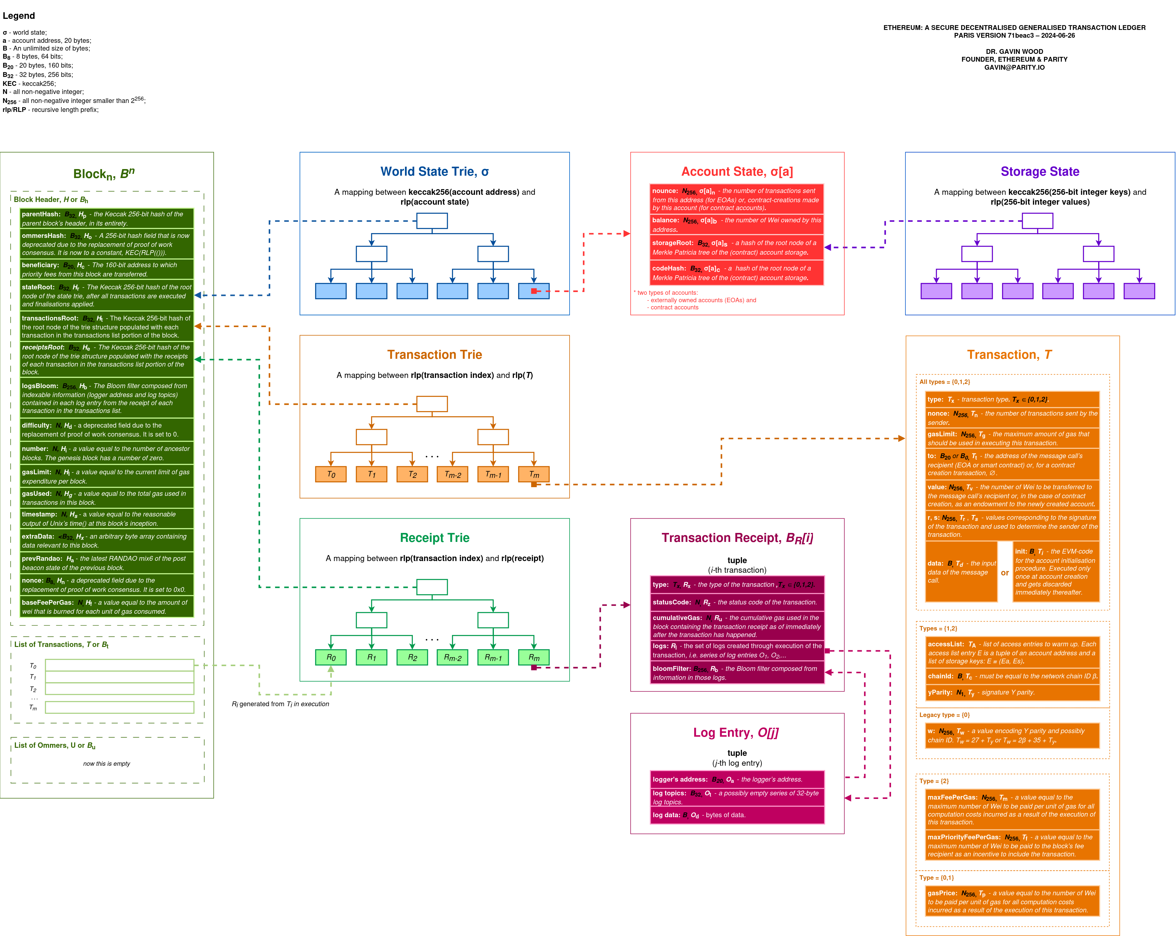
# Block Structure

The figure below illustrates the block structure of a Blade block which conforms to Ethereum.

<figure><img src="https://3820615377-files.gitbook.io/~/files/v0/b/gitbook-x-prod.appspot.com/o/spaces%2F4nX3GBMyBbMsZe2u4kJt%2Fuploads%2Fgit-blob-72c208fb775372e2df8c28a732efa9765c3e18b5%2FBlock%20Structure%20Image.png?alt=media" alt=""><figcaption><p>Block Structure Diagram</p></figcaption></figure>

A high resolution block structure diagram image:

{% file src="/files/nCNH9LtmHA1GYrGKBlPe" %}


# State Tries

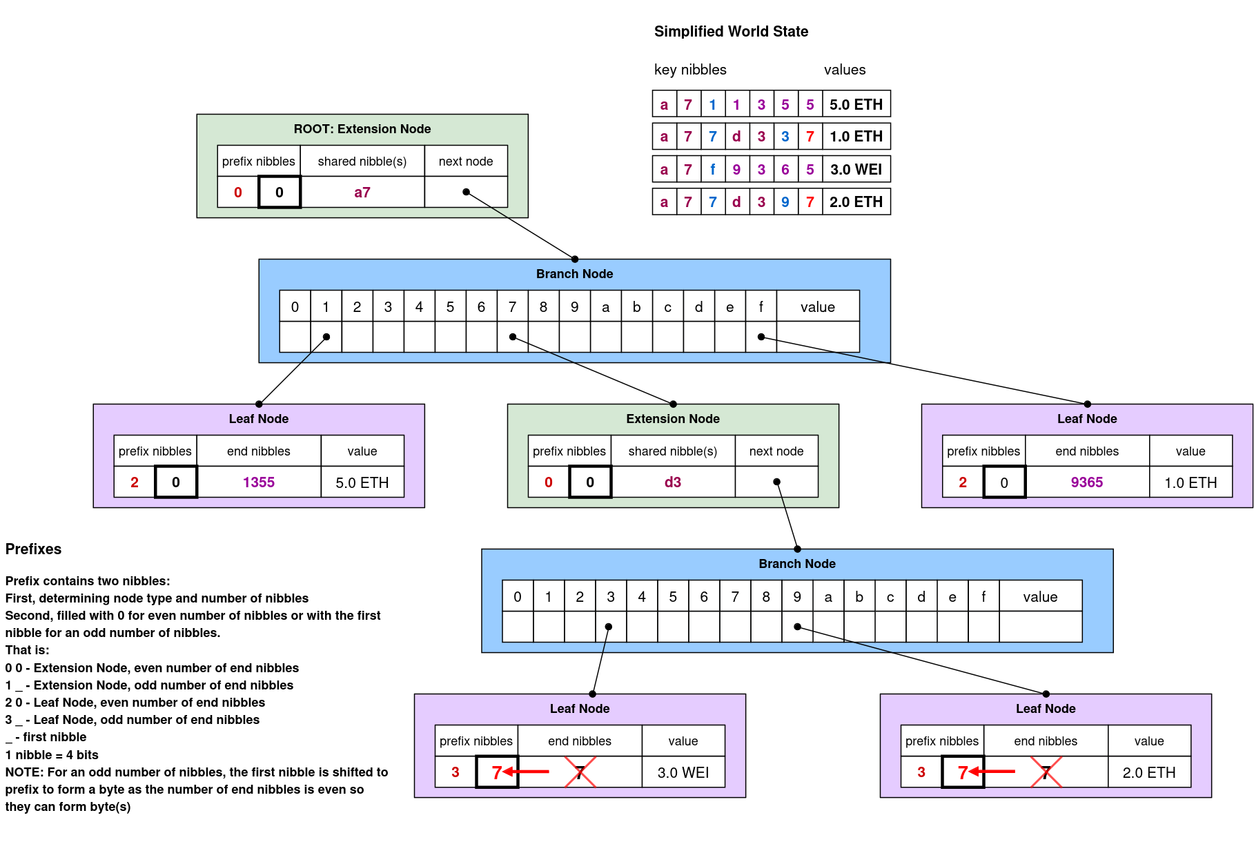
World State Trie

The **World State Trie** (WST), also called the **State Trie** or **Global State Trie**, is a critical data structure that represents the current state of all accounts on the Ethereum network.

* The trie is persisted to disk.
* All of the values are **RLP-serialized accounts**.

The figure below shows an example of world state trie with detailed node structure.

<figure><img src="https://3820615377-files.gitbook.io/~/files/v0/b/gitbook-x-prod.appspot.com/o/spaces%2F4nX3GBMyBbMsZe2u4kJt%2Fuploads%2Fgit-blob-fff5b54e9530246fa5a942b7d3e794040adeb315%2Fsystem_architecture-world%20state.drawio(4).png?alt=media" alt=""><figcaption><p>World State Trie Example</p></figcaption></figure>

***

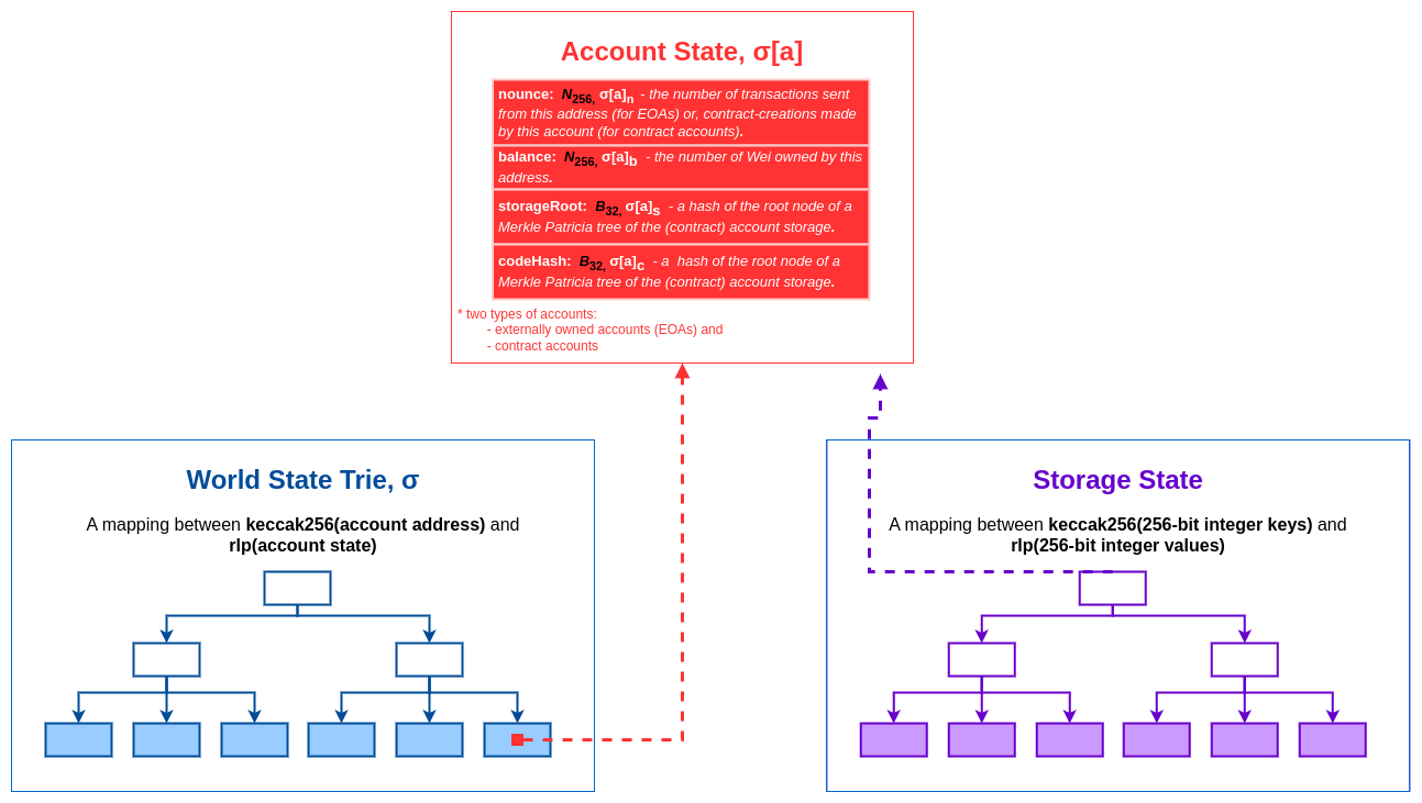
## Account Storage Trie

The **Account Storage Trie** is a data structure used to store the persistent data of a smart contract. It is a **Merkle Patricia Trie**, like the World State Trie, and it maps storage keys to storage values for a specific contract account.

More details:

* Each contract account on Ethereum has its **own Account Storage Trie**, which stores the contract's persistent state variables.
* The storage trie is specific to a single contract and is **separate from the World State Trie**, which stores the global state of all accounts.
* The **root hash** of the Account Storage Trie is stored in the `storageRoot` field of the contract's account state (in the World State Trie).

<figure><img src="https://3820615377-files.gitbook.io/~/files/v0/b/gitbook-x-prod.appspot.com/o/spaces%2F4nX3GBMyBbMsZe2u4kJt%2Fuploads%2Fgit-blob-379f7385d073d12a366493ab75d66031d048c33d%2Faccount-storage-trie.png?alt=media" alt=""><figcaption><p>Account storage trie example.</p></figcaption></figure>

***

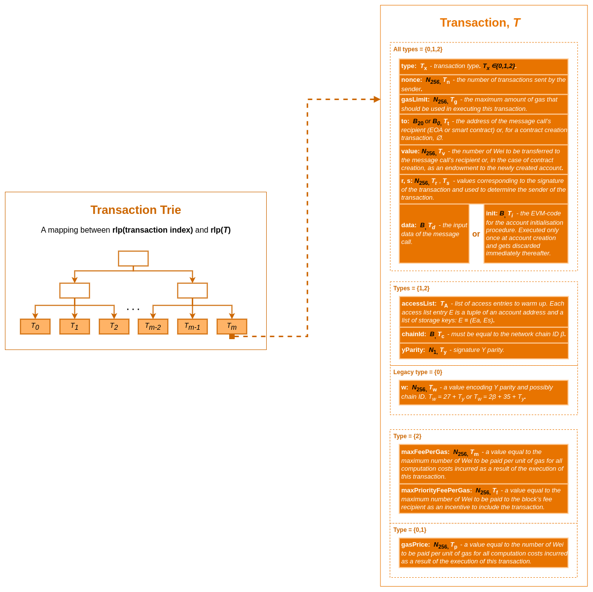
## Transaction Trie

In the context of Ethereum, the **Transaction Trie** is a data structure used to store and organize all the transactions included in a specific block.

* Each block contains a Transaction Trie that holds all the transactions in that block.
* The transactions are indexed by their position in the block and are RLP-encoded.
* The root hash of this trie is stored in the block header (`transactionsRoot` field).

<figure><img src="https://3820615377-files.gitbook.io/~/files/v0/b/gitbook-x-prod.appspot.com/o/spaces%2F4nX3GBMyBbMsZe2u4kJt%2Fuploads%2Fgit-blob-55761e410502871e1ccd23e53f65e248a2964c60%2Ftransaction-trie.png?alt=media" alt=""><figcaption><p>Transaction trie example.</p></figcaption></figure>

***

## Transaction Receipt Trie

The **Transaction Receipt Trie** records the **receipts (outcomes)** of transactions.

* A **receipt** is the result of a transaction that was executed successfully.
* Each receipt includes:
  * The **transaction hash**
  * **Block number**
  * **Amount of gas used**
  * **Contract address** (if a new contract was created)
  * Other execution metadata
* Like the Transaction Trie, this is a Merkle Patricia Trie whose root hash is stored in the block header (`receiptsRoot` field).

<figure><img src="https://3820615377-files.gitbook.io/~/files/v0/b/gitbook-x-prod.appspot.com/o/spaces%2F4nX3GBMyBbMsZe2u4kJt%2Fuploads%2Fgit-blob-e0e95215da890bece677de60a0faec02c5d23a57%2Freceipt-trie.png?alt=media" alt=""><figcaption><p>Transaction receipt trie example.</p></figcaption></figure>


# Data Structures in Blade

This chapter provides a mapping between the main Ethereum data structures explained above and their implementation in **Blade**, the Ethereum client.

We answer the following:

* Where these data structures are located in the Blade source code?
* How they are manipulated or updated during runtime?
* The correspondence between Ethereum’s conceptual structures (e.g., tries, receipts) and Blade's internal representations.

This serves as a bridge between theoretical Ethereum architecture and its practical implementation in Blade.


# Storage

The entire **WST** is stored in a **key-value database** persisted on disk.

Storage serves as an abstraction layer for accessing the databases used to persist blockchain data.\
Blade supports both GoLevelDb and Pebble database for persisting blockchain data. Pebble is set by default.

The following image presents:

* The main **Storage API** functions
* A **high-level design diagram** of the storage layer

<figure><img src="https://3820615377-files.gitbook.io/~/files/v0/b/gitbook-x-prod.appspot.com/o/spaces%2F4nX3GBMyBbMsZe2u4kJt%2Fuploads%2Fgit-blob-7642b78e5b58f2b9fd35559dd13109a3ffdf3fd9%2Fstorage.png?alt=media" alt=""><figcaption><p>Storage example</p></figcaption></figure>


# State

The blockchain **WST** is accessed at the application level through a `State` object.

* `State` is a **wrapper around the Storage** layer.
* It includes an **LRU cache** to optimize access to disk-based data.
* The `State` object is used to **create a WST snapshot** at a specific root address, allowing for manipulation of the WST at that point in time.

The following class diagram illustrates the most important subset of methods provided by the `State` object:

<figure><img src="https://3820615377-files.gitbook.io/~/files/v0/b/gitbook-x-prod.appspot.com/o/spaces%2F4nX3GBMyBbMsZe2u4kJt%2Fuploads%2Fgit-blob-c7f9606daaf92e8eb0c3d179dafd6c80818181ea%2Fstate.png?alt=media" alt=""><figcaption><p>A table listing the key methods.</p></figcaption></figure>


# Snapshot

A **Snapshot** represents the state of a **subtree of the WST** at a specific moment in time.

* The **subtrie** is defined by specifying a **root hash**.
* It enables:
  * **Reading** a subset of blockchain state data
  * **Running transactions** against that state
  * **Committing** the updated changes back to storage

Snapshots are created using a `State` object, which provides the interface for snapshot initialization and manipulation.


# State Txn

`State.Txn` is a wrapper class around [`hashicorp/go-immutable-radix`](https://github.com/hashicorp/go-immutable-radix) (**iradix**).

* It is used to perform temporary, in-memory modifications to the state.
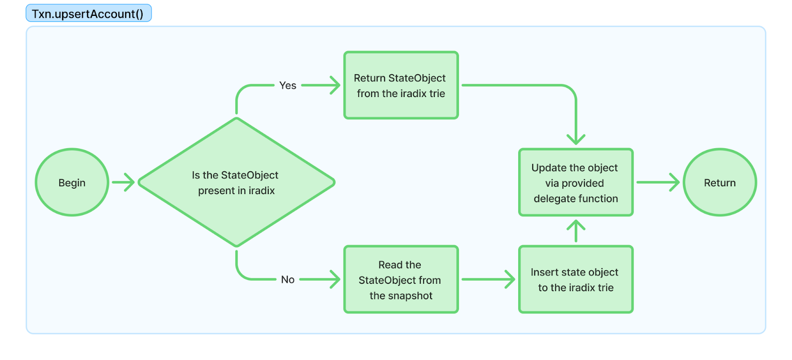
* The `Txn.upsertAccount()` function is used to modify existing nodes, as illustrated in the chart below:

<figure><img src="https://3820615377-files.gitbook.io/~/files/v0/b/gitbook-x-prod.appspot.com/o/spaces%2F4nX3GBMyBbMsZe2u4kJt%2Fuploads%2Fgit-blob-f9ce22640435c36d63e7378aa0658032cbba1015%2Fstate-txn1.png?alt=media" alt=""><figcaption><p>Flowchart of Txn.upsertAccount()</p></figcaption></figure>

## How It Works

When updating a `Txn`:

* The original **Snapshot** remains unchanged.
* All changes are stored in the **iradix trie**, which is immutable and efficient for such use cases.

## Data Members

`state.Txn` contains the following data members:

* \[List key fields or describe members here, if known or applicable]

<figure><img src="https://3820615377-files.gitbook.io/~/files/v0/b/gitbook-x-prod.appspot.com/o/spaces%2F4nX3GBMyBbMsZe2u4kJt%2Fuploads%2Fgit-blob-de219538596a9cc13312348862d815cc788cdd4b%2Fstate-txn2.png?alt=media" alt=""><figcaption><p>state.Txn data structure.</p></figcaption></figure>

## Example

An example structure of the **iradix trie** used within `state.Txn` is shown in the following image:

<figure><img src="https://3820615377-files.gitbook.io/~/files/v0/b/gitbook-x-prod.appspot.com/o/spaces%2F4nX3GBMyBbMsZe2u4kJt%2Fuploads%2Fgit-blob-7bd056f95fbd94a9f7649caefea4657e01992f44%2FiRadix-trie.png?alt=media" alt=""><figcaption><p>iRadix trie example.</p></figcaption></figure>


# State Transition

A `Transition` instance is responsible for processing a **series of transactions** sequentially on a given **snapshot**.

## Structure

* A `Transition` consists of:
  * A **snapshot** (the base state on which the transition operates)
  * A `Txn` instance, which references the **same snapshot**

## Behavior

* During transaction execution, the `Transition` maintains a set of **receipts**.
* All **read** or **update** operations on the WST are performed through the `transition.state.Txn` object.
* `state.Txn` is an instance of an iradix, ensuring:
  * The original **snapshot remains unchanged**
  * **All changes are captured** in an isolated, accessible structure

## Diagram

The structure and data members of the `Transition` object are shown in the following image:

<figure><img src="https://3820615377-files.gitbook.io/~/files/v0/b/gitbook-x-prod.appspot.com/o/spaces%2F4nX3GBMyBbMsZe2u4kJt%2Fuploads%2Fgit-blob-7e7c37980ad13752e4a8bebf933f4596e14a3193%2Fstate-transition.png?alt=media" alt=""><figcaption><p>Transition data structure.</p></figcaption></figure>


# World State Trie Update Dataflow

This chapter illustrates the **execution flow** when a set of transactions is executed against a specific **WST** during block building.

> 📝 **Note:** The process of selecting the block proposer, transaction set, etc., is out of scope for this document.\
> The description begins from the point where the **parent block** and **transaction set** are already determined.

***

## Block Candidate

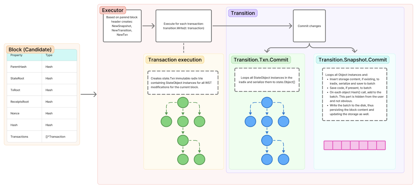
A block candidate contains several data members (some omitted for brevity).

<figure><img src="https://3820615377-files.gitbook.io/~/files/v0/b/gitbook-x-prod.appspot.com/o/spaces%2F4nX3GBMyBbMsZe2u4kJt%2Fuploads%2Fgit-blob-0023daf33b985f0d3e0b601bf480df44a53f043d%2Fwst-update-data1.png?alt=media" alt=""><figcaption><p>Data structure of block candidate</p></figcaption></figure>

***

## Execution Overview

1. The **executor** creates:
   * A new `Snapshot`
   * A new `Transition`
   * A new `Txn`
2. The `Transition` is then used to **apply each transaction** to `state.Txn`.
   * At this stage:
     * `state.Txn` reads all the required data from **storage** via the **snapshot**
     * It updates the state
     * The updated data is stored in the **`iradix` field** of `state.Txn`

***

## Committing Changes

If all transactions execute successfully, the changes are committed to storage using `Transition.Commit()`.\
This consists of two main steps:

### 1. `Transition.Txn.Commit()`

* Walks through the `Transition.Txn.txn` **iradix trie**
* Serializes all modified `StateObject` instances
* Returns them as an array of `state.Object` instances

### 2. `Transition.Snapshot.Commit()`

* Writes the `state.Object[]` to persistent storage
* This process includes:
  * Creating an empty `state.trie.Txn` of type `itrie.Txn`
  * Populating `itrie.Txn` with all the prepared `state.Object` instances
  * Performing **RLP serialization** of the complete `itrie.Txn`
  * Storing the serialized trie to the persistent database using its **hash as the key**

This results in the creation of the **World State Trie**, as described in Ethereum's general documentation.

During this process, **Smart Contract (SC) storage** is converted from a **single-dimensional array-like structure** (used by the EVM) to an **`itrie.Txn`**, forming the **Account Storage Trie** as defined in Ethereum.

<figure><img src="https://3820615377-files.gitbook.io/~/files/v0/b/gitbook-x-prod.appspot.com/o/spaces%2F4nX3GBMyBbMsZe2u4kJt%2Fuploads%2Fgit-blob-8d3a9864c743fff31ca492294aa95a7155dfeee6%2Fwst-update-data2.png?alt=media" alt=""><figcaption></figcaption></figure>

***

## Batch Writing Optimization

To enhance performance:

* All changes are first written to a **batch**
* Only at the end of processing are the changes **committed to persistent storage**

### Trie Serialization

Serialization of the trie is handled in the `itrie.Txn.Hash()` function, using logic like the following:

```go
tmp := val.MarshalTo(nil)

...

root = h.hash.Sum(nil)

if t.batch != nil {
    t.batch.Put(root, tmp)
}

```

## Transactions Trie and Receipts Trie in Ethereum

Ethereum uses a **minimalistic storage method** to manage transactions and receipts by storing their **Merkle root hashes** in the block header. This enables efficient and secure verification without storing all data directly in the header.

### Transactions Trie

* The **Transactions Trie** is stored as a hash in the block header field called `TxRoot`.
* This allows the full list of transactions in a block to be verified by computing the Merkle root of the transactions and comparing it to `TxRoot`.
* The root hash is computed using the `CalculateTransactionsRoot()` function.

### Receipts Trie

* The **Receipts Trie** is similarly stored in the block header as the `ReceiptsRoot` field.
* This allows verification of all transaction receipts within the block.
* The root hash of the receipts is calculated using the `CalculateReceiptsRoot()` function.

### Internal Structures and WST Updates

The following diagram illustrates how these internal structures are used in the updating of the **World State Trie (WST)**:

<figure><img src="https://3820615377-files.gitbook.io/~/files/v0/b/gitbook-x-prod.appspot.com/o/spaces%2F4nX3GBMyBbMsZe2u4kJt%2Fuploads%2Fgit-blob-81a652618117e5f357079cdb840ee4a606561732%2Fwst-update-data3.png?alt=media" alt=""><figcaption><p>Internal structures used for updating WST</p></figcaption></figure>

***

By leveraging these Merkle Patricia Tries, Ethereum ensures integrity, verification efficiency, and data minimization in its blockchain architecture.


# Transaction Pool

In this section transaction pool (TxPool) is described together with its instantiation, role in the block creation process and the way how new transactions are added to it.

The transaction pool, `TxPool`, is an in-memory structure that manages the incoming transactions for processing. It maintains a list of unprocessed transactions and ensures they conform to specific constraints before entering the pool.

## Model <a href="#z48tsps1kxeg" id="z48tsps1kxeg"></a>

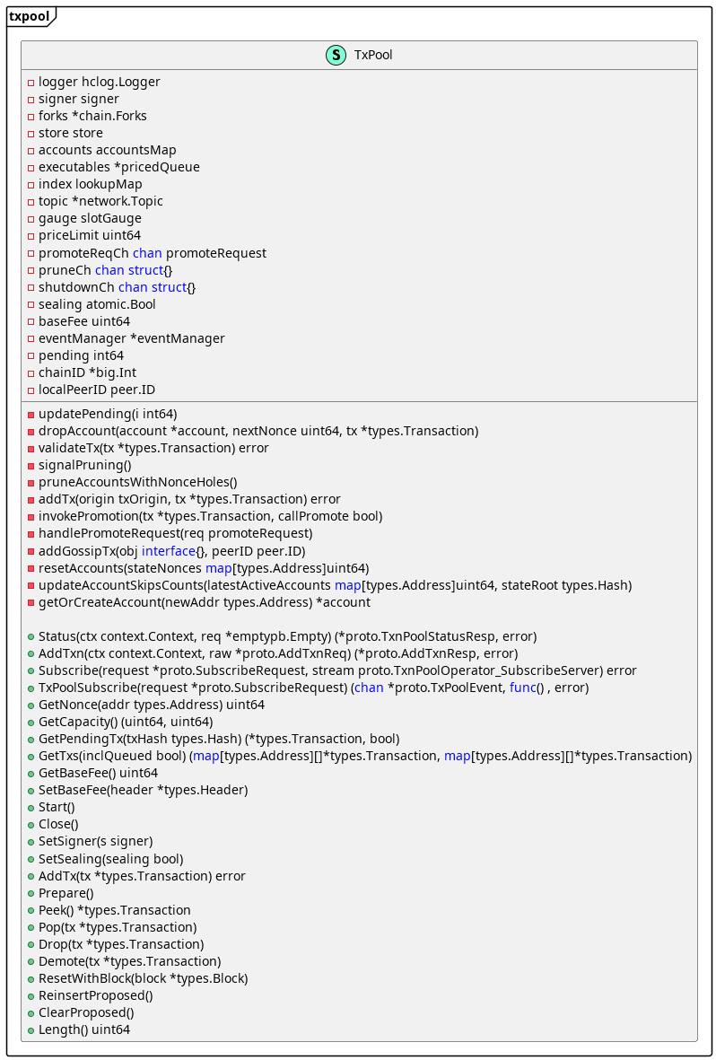
Details of `TxPool` structure are shown in the *TxPool Structure* diagram.

<figure><img src="https://3820615377-files.gitbook.io/~/files/v0/b/gitbook-x-prod.appspot.com/o/spaces%2F4nX3GBMyBbMsZe2u4kJt%2Fuploads%2Fgit-blob-586daacae31db90b6f243fccfbf0a95fb8dc8907%2Ftxpool_struct.png?alt=media" alt=""><figcaption><p>TxPool Structure</p></figcaption></figure>

TxPool fields:

* **`logger`** - logger interface that defines applicable logger methods,
* **`signer`** *-* signer interface that defines a transaction sender,
* **`forks`** - represents a map which contains all forks and their starting blocks from genesis,
* **`store`** *-* interface defines State helper methods the `TxPool` should have access to,
* **`accounts`** - map of all accounts registered by the pool,
* **`executables`** - represents all the primaries (i.e. transactions ready for execution) sorted by max gas price,
* **`index`** - lookup map keeping track of all transactions present in the pool,
* **`topic`** - networking stack,
* **`gauge`** - gauge for measuring pool capacity,
* **`priceLimit`** - represents a lower threshold for gas price,
* **`sealing`** - flag indicating if the current node is a sealer (validator), and should therefore gossip transactions,
* **`baseFee`** - represents the base fee of the current head. This is needed to sort transactions by price,
* **`eventManager`** - event manager for `TxPool` events,
* **`pending`** - represents the list of pending and ready transactions. This variable is accessed with atomics,
* **`chainID`** - chain ID,
* **`localPeerID`** - represents the peer ID of the local node that is running the `TxPool`.

Some of the main `TxPool` methods include:

* **`NewTxPool`** - `NewTxPool` creates and returns a new pool for processing incoming transactions,
* **`Start`** *-* runs the pool's main loop in the background. On each request received, the appropriate handler is invoked in a separate goroutine,
* **`Close`** - shuts down the pool's main loop,
* **`SetSigner`** - sets the signer the pool will use // to validate a transaction's signature,
* **`AddTx`** - adds a new transaction to the pool (sent from json-RPC/gRPC endpoints) and broadcasts it to the network (if enabled),
* **`Prepare`** - generates all the transactions ready for execution. (primaries),
* **`Peek`** - returns the best-price selected transaction ready for execution,
* **`Pop`** - removes the given transaction from the associated promoted queue (account). It will update `executables` with the next primary from that account (if any),
* **`Drop`** - clears the entire account associated with the given transaction and reverts its next (expected) nonce,
* **`Demote`** - excludes an account from being further processed during block building due to a recoverable error. If an account has been demoted too many times, it is Dropped instead,
* **`ResetWithBlock`** *-* processes the transactions from the newly finalized block to sync the pool with the new state,
* **`ReinsertProposed`** - returns all transactions from the accounts proposed queue to the promoted queue. It is called from consensus algorithm, when new round > 0 starts or when current sequence is cancelled.
* **`ClearProposed`** *-* clears accounts proposed queue when round 0 starts. It is called from consensus algorithm.

## TxPool Instantiation <a href="#id-6i4namyk3dh0" id="id-6i4namyk3dh0"></a>

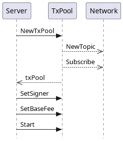
Every node has a single instance of `TxPool` in-memory structure, which is created on the node startup. `NewTxPool` method is in charge of creating a new `TxPool` populated with static and dynamic content. Afterwards, transaction `TxPool`'s signer is created and assigned, base fee is determined and assigned, and TxPool is started. `TxPool` listens for a shutdown event, prunes accounts with nonce holes and handles promoted transactions.

<figure><img src="https://3820615377-files.gitbook.io/~/files/v0/b/gitbook-x-prod.appspot.com/o/spaces%2F4nX3GBMyBbMsZe2u4kJt%2Fuploads%2Fgit-blob-cbbcb3353521238e50f967e6f1ac3a69e67cec51%2Ftxpool_instantiation_sequence%20(1).png?alt=media" alt=""><figcaption><p>TxPool Instantiation Process Sequence Diagram</p></figcaption></figure>

## Role of TxPool in Block Creation <a href="#id-5qvuftlg7knu" id="id-5qvuftlg7knu"></a>

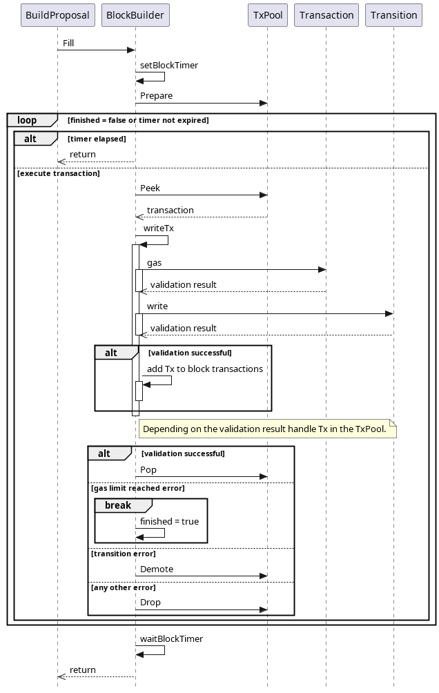
`BlockBuilder`'s `Fill` method uses `TxPool` to fill the block with transactions taken from`TxPool`. Each transaction is validated one by one, and valid transactions are added to the`BlockBuilder`'s list of transactions. Transactions are validated until a predefined timer (for block creation) expires or a predefined gas (for prepared transactions) is spent.

*Block Creation Sequence Diagram* gives a detailed overview of block creation actions. `BlockBuilder`'s is in charge of:

* creating a block timer that limits the time interval allowed for block creation, and
* preparing transactions in `TxPool`, where all transactions ready for execution are sorted descending by best price (i.e., transaction fee), giving an advantage to more expensive ones.

After the block timer is set and transactions are prepared, transactions are taken from the `TxPool` and checked for their validity during the transaction write process. The process adds a valid transaction to the block and removes it from the `TXPool`.

If the transaction is invalid, then, depending on the error, the transaction is dropped or demoted from the `TxPool`. A dropped transaction assumes that its entire account is cleared and its nonce is reverted, while a demoted transaction assumes that its account is excluded from further processing during block building due to a recoverable error. Still, if an account is demoted too many times, it will be dropped instead.

If the gas limit is reached, the block creation is finished. Otherwise, the process is repeated with the next transaction from the `TxPool` until the predefined time expires.

<figure><img src="https://3820615377-files.gitbook.io/~/files/v0/b/gitbook-x-prod.appspot.com/o/spaces%2F4nX3GBMyBbMsZe2u4kJt%2Fuploads%2Fgit-blob-079474dcdc8c614b9e4485fef0c908a9f60d338e%2Ftxpool_block_creation_sequence%20(1).png?alt=media" alt=""><figcaption><p>Block Creation Sequence Diagram</p></figcaption></figure>

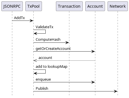
## Adding Transactions to TxPool <a href="#n6hacokagz2u" id="n6hacokagz2u"></a>

As the process of `TxPool` instantiation and its role in block creation are described, let us see how `TxPool` is populated with new (potential) transactions.

The main source of new transactions is the `JSONRPC` component. This component, more precisely a remote procedure call protocol, is used for communication of Blade nodes with the outer world. Since `JSONRPC` utilizes JSON, it relies on the same type system.

`TxPool` receives new transactions through its `SendRawTransaction` method via the `JSONRPC` component. The method calls `TxPool`'s `AddTx` to pass received transactions. `AddTx` conducts a series of validation checks on a transaction. When validation fails, an appropriate error message is thrown, and the transaction is skipped from being added to TxPool.

Transaction validations include:

* **state transaction check** - as transactions with `StateTxPType` transaction type are not expected to be added to the `TxPool`,
* **transaction size check** - as a transaction size cannot exceed 128 kB, which helps to overcome DOS attacks,
* **transaction value check** - as transactions strictly have positive values,
* **smart contract deployment check** - checks if a transaction can deploy a smart contract,
* **forks check** - depending on the transaction type and given fork, it checks whether the transaction is allowed:
  * **`AccessListTxType`** - this transaction type is applicable only when Berlin hardfork (eip-2930) is enabled and the transaction is not underpriced,
  * **`DinamicFeeTxType`** - this transaction type is applicable only when London hardfork is enabled, where GasFeeCap and GasTipCap fields have correct values and the transaction is not underpriced,
  * **other transaction types** - these transaction types are applicable only when London hardfork is enabled and the transaction is not underpriced,
* **transaction underpriced check** - as underpriced transactions are not allowed in regards to price limits,
* **transaction pool signer check** - as the transaction pool has to be signed properly, i.e., the transaction pool sender (i.e., signer) has to be present,
* **transaction signer check** - as the transaction's `From` field, if set, must match the signer. Otherwise, it is set to signer value.
* **transaction block gas limit check** - as a transaction gas must not exceed the latest block gas limit
* **transaction intrinsic gas check** - as a transaction must have more gas than the basic transaction fee (intrinsic gas is a constant transaction fee),
* **transaction nonce check** - as transaction nonce cannot be lower than account nonce,
* **sender funds check** - as a transaction sender must have enough funds to execute the transaction.

When a validation fails, an appropriate error is raised, and the transaction is skipped. When all checks pass successfully, the following actions are taken:

* chain ID is set for `DinamicFeeTxType` transactions,
* transaction hash is calculated,
* account (of transaction sender) is added to `TxPool`, if not already there,
* in a case of high pressure in the pool, transaction nonce is checked against account nonce, and if the nonce was not expected transaction is rejected,
* a check is done to find an existing transaction with the same nonce for the current account and the same hash, in which case the transaction is rejected as well,
* if a transaction with the same nonce is found, with a different hash but having the same or better gas price, the transaction is also rejected,
* when a transaction with the same nonce is not found,
  * if the account has reached a maximum number of transactions and the transaction nonce differs from account nonce, transaction is rejected,
  * transaction nonce cannot be lower than account nonce, in that case the transaction is rejected
* if there is an existing transaction with the same nonce, then the new transaction tries to occupy its slot without exceeding the transaction pool limits. If a transaction overflow happens, the transaction is rejected.
* the new transaction is then added to the `lookupMap,` and the old one with the same nonce is removed (if it existed),
* the transaction is then added or replaced in the current account,
* <mark style="color:red;">a promotion event is raised when the transaction nonce is less than or equal to the account nonce.</mark>
* later, transactions are published to other nodes through the network (assuming that a node has the ability to send transactions and subscriptions are present). Network nodes handle received transactions through `TxPool`'s `addGossipTx` handler method, where they add transactions to their pool.

<figure><img src="https://3820615377-files.gitbook.io/~/files/v0/b/gitbook-x-prod.appspot.com/o/spaces%2F4nX3GBMyBbMsZe2u4kJt%2Fuploads%2Fgit-blob-d02659b846eb3d2571a507deb248ce5ee4ce6825%2Ftxpool_add_tx_sequence.png?alt=media" alt=""><figcaption><p>Adding Transaction to TxPool Sequence Diagram</p></figcaption></figure>


# Block Creation Process

In this section block creation process is described together with all related components.

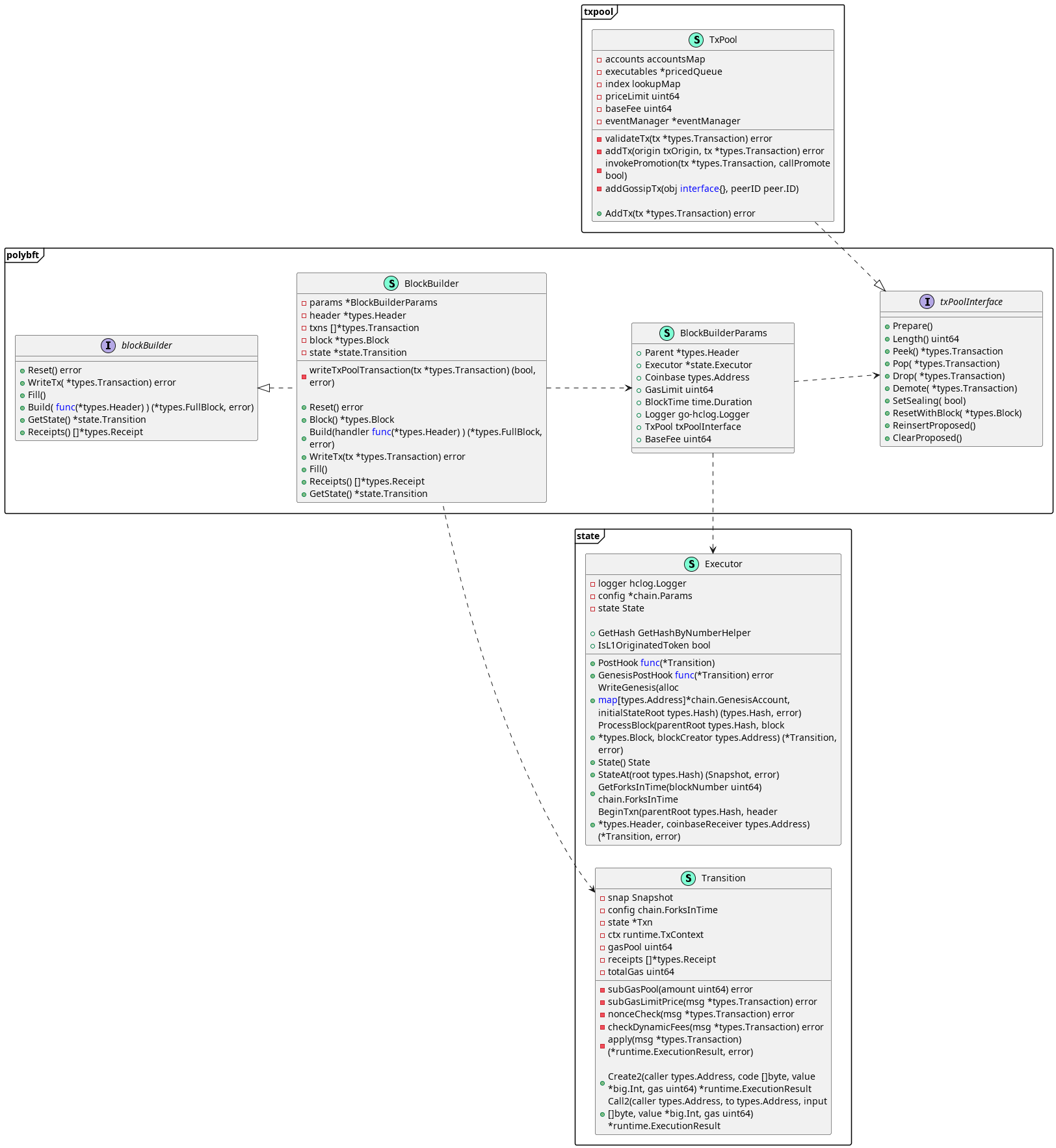
Block creation is the essence of the blockchain system. The following figure shows all the components involved in the process (for clarity reasons, some fields and methods in the structures are omitted):

<figure><img src="https://3820615377-files.gitbook.io/~/files/v0/b/gitbook-x-prod.appspot.com/o/spaces%2F4nX3GBMyBbMsZe2u4kJt%2Fuploads%2Fgit-blob-73195e880bcfe2711c7a2520e37a1ddfbac5a2b8%2Fpolybft_block_creation.png?alt=media" alt=""><figcaption><p>Elements of the Block Creation Process</p></figcaption></figure>

The `BlockBuilder` represents one of the most important components of the system, which, as the name suggests, enables the creation of a block. This component possesses specific configuration parameters (`BlockBuilderParams`), whose values are set during its instantiation by calling the `NewBlockBuilder` method. The key parameters and their meanings are outlined below:

1. **`parent`** - header of the previous (parent) block.
2. **`executor`** - auxiliary component invoked by `BlockBuilder` during block creation.
3. **`gasLimit`** - maximum amount of gas in the block.
4. **`blockTime`** - maximum time for block creation.
5. **`txPool`** - reference to the transaction pool from which transactions are selected.
6. **`baseFee`**

In addition to these immutable parameters during block creation, there are specific fields in the `BlockBuilder` structure that reflect the current state of the block being created. The content of these fields changes as the block creation process progresses. These include:

1. **`header`** - the block header,
2. **`txns`** - a list of selected transactions for the block,
3. **`block`** - a reference to the block itself (set only after the block is completely created), and
4. **`state`** - an additional auxiliary component (a.k.a.`Transition`) enabling the transition from one state to the next during block creation.

To fully grasp what follows, it is crucial to understand that block creation is based on state changes. The initial state is the last state from the previous block. Transitioning to the next state occurs when selecting a new valid transaction to include in the block. Therefore, the number of transactions in the block determine how many state transitions are necessary. The previously mentioned `Transition` component is responsible for verifying the validity of the transaction and, if everything is correct, transitioning to the next state.

The `BlockBuilder` has several methods. Below, each method is explained in sequence, illustrating how they impact the block creation process. The order in which they are mentioned reflects the sequence in which they must be called during block creation. The methods are as follows:

1. **`NewBlockBuilder`**
2. **`Reset`**
3. **`Fill`**
4. **`WriteTx`**
5. **`Build`**

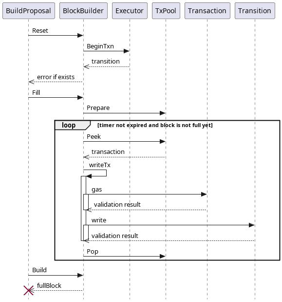
### `Reset`

The first method to call after creating a `BlockBuilder` is `Reset`. This method is responsible for setting all fields of the `BlockBuilder` related to the currently created block to their initial values. The set of transactions chosen for the block is set to an empty list, the header is filled with values that can be calculated at the given moment, the block reference does not exist (set to nil), while the `transition` object, using the `Executor` parameter, is created with all elements necessary for proper transaction validation and potential transition to the next state. Some of these elements include the total gas amount in the block, allow lists, currently used gas (set to 0), reference to EVM, fork-related information, initial state (the last state from the previous block), etc.

<figure><img src="https://3820615377-files.gitbook.io/~/files/v0/b/gitbook-x-prod.appspot.com/o/spaces%2F4nX3GBMyBbMsZe2u4kJt%2Fuploads%2Fgit-blob-b5db07b6197022a4963434b60420e3b27e9a6ccd%2Fpolybft_block_creation_sequence%20(3).png?alt=media" alt=""><figcaption><p>Block Creation Sequence Diagram</p></figcaption></figure>

### Fill

Once the initial state is set, the next method to call is `Fill`. It takes one transaction at a time from the transaction pool, checks its validity, and if everything is fine, records it in the list of selected transactions for the given block. It is important to understand that at this point, the transaction is not yet placed in the block but only entered into the list of selected transactions. There are two possible conditions for completing the execution of this method:

* the timer expires, i.e., the time allotted for block creation ends, or
* the sum of gas for all selected transactions exceeds the maximum gas limit that can be in the block.

Upon calling the `Fill` method, the timer is started, and the `Prepare` method of the transaction pool is invoked. This method allows preparing the transaction pool by sorting transactions by their fee. The next step is initiating an infinite for loop where, in each iteration, by calling the `Peek` method of the transaction pool, one transaction is taken. The transaction is then validated, and if everything is fine, a state change is executed, and the transaction is recorded in the list of selected transactions. This is achieved by calling the third method of `BlockBuilder` (`WriteTx`) for each transaction. If everything goes well, the transaction is removed from the transaction pool using the `Pop` method, and the loop proceeds to the next iteration (if possible). Exiting the for loop is accomplished by satisfying one of the previously mentioned two conditions.

### WriteTx

The `WriteTx` method of `BlockBuilder` is invoked for each transaction that may potentially be chosen for later inclusion in the block. Whether it will be chosen or not depends on its validity. The validity is checked using the `Write` method of the `transition` object. In other words, for each transaction from the `Fill` method, the `WriteTx` method of `BlockBuilder` is called first, and then from `WriteTx`, the `Write` method of the `transition` object is called. If everything is correct in the `Write` method, the transaction is valid, and within it, the transition to the next state occurs. Upon returning to `WriteTx`, with the condition that everything is correct, the transaction is recorded in the list of selected transactions. An invalid transaction will not lead to the interruption of block creation; instead, it is discarded, and the process remains in the current state.

> The execution of the transition (transaction validation and transition to the next state), or the Write method, represents the core of the new block creation process.

The first thing accomplished within the `Write` method is taking a Snapshot of the current state. This allows for a safe return to the previous, secure state in case the transition fails (i.e., unsuccessful processing of a given transaction). After taking the Snapshot, the process of transaction validation and gradual transition to the next state begins. The procedure is as follows:

1. Determine the type of transaction and, depending on that, perform different checks.
   1. Checks differ based on whether it is (i) a state transaction or (ii) a legacy transaction / dynamic fee transaction.
   2. The most crucial check is related to gas and sender's funds.
   3. State transactions must not have any gas spending set.
   4. Legacy and dynamic fee transactions must be configured so that the sender has enough funds to pay the maximum gas defined in the transaction (in other words, the sender must have funds to pay the maximum gas even if he would not spend it all).
   5. If the sender has enough funds, the amount for the maximum gas is deducted; otherwise, the transaction is invalid, and further steps are not taken.
2. Subtract the maximum gas amount of the transaction from the total gas that can appear in the block.
   1. If the result of this calculation is a negative number, the transaction is rejected, and further steps are not taken.
   2. This simultaneously satisfies one of the conditions for completing the `Fill` method.
3. Calculate the initial, basic, guaranteed gas consumption (intrinsic gas) that depends on whether it is a transaction creating a smart contract, calling a smart contract, or transferring funds.
4. Check if this gas amount is less than the maximum set in the transaction (max gas).
   1. If not, the transaction is invalid, and further steps are not taken.
5. If it is not a transaction just transferring funds, call the constructor or function of the smart contract, consuming additional gas (must be less than max gas - intrinsic gas).
6. Since funds were initially deducted from the sender's balance as if spending the maximum gas, at this point, funds for the remaining gas are returned.
7. Payment of potential fees associated with dynamic transactions.
8. Since at the beginning, the maximum gas in the transaction was deducted from the maximum gas that can be in the block, at this point, the remaining gas is returned to that gas pool.

Upon completion of step 8, the transaction is marked as valid, simultaneously completing the transition to the next state. As a result, a receipt is generated. Together with other receipts, it is later added to the block header and serves as confirmation that the transaction execution occurred without errors. Finally, upon returning to the `WriteTx` method, the transaction is added to the list of transactions selected for inclusion in the block.

### Build

The last method of `BlockBuilder` to be called is `Build`. Its role is to create a concrete full block based on the content of previously configured fields in `BlockBuilder`. Within this method, the previously selected transactions are inserted into the block, the Merkle Tree Root is calculated for transactions, receipts, and transition states, they are all added to the block header, etc.


# Consensus Mechanism

In order to enable a transition to the next state within a system consisting of an unlimited number of asynchronous nodes, it is necessary to establish a mechanism that coordinates the node. The mechanism determines how a set of changes is applied to all network participants. For this reason, when a new blockchain network is created, one of the most important consensus rules to be defined is how participants in the network reach an agreement on the next block that will be accepted in the chain.

Despite the presence of various widely accepted solutions in the contemporary blockchain networks, it is hard to find one that satisfies all requirements of the Blade system. For example, if we analyze the most dominant networks, Bitcoin's Proof-of-Work (PoW) consensus algorithm, while the most secure, requires a significant amount of electrical energy and has relatively low throughput. On the other hand, decentralization of Ethereum's Proof-of-Stake (PoS) consensus algorithm is quite questionable. The goal of a Blade consensus algorithm is to make a balance between these two approaches. For this reason, one of the Proof-of-Authority (PoA) solutions was adopted - the Istanbul Byzantine Fault Tolerant (IBFT) 2.0 consensus algorithm.

Leveraging the IBFT 2.0 consensus algorithm not only enables the Blade system to have a commendable balance of security and throughput but also achieves this at a remarkably low energy cost. Furthermore, the introduction of a dynamic set of validators, determined through a voting mechanism, facilitates the desired decentralization.

A critical prerequisite for the successful functioning of IBFT 2.0, as all other Byzantine Fault Tolerant (BFT) algorithms operating in a partially synchronized state, is that the total number of validator nodes engaged in the decision-making process must be at least **3F+1.** **F** signifies the quantity of malicious participants. The security profile in these algorithms is characterized by extremes. To elaborate, fulfillment of the mentioned condition maximizes security, whereas failure to meet it results in a complete collapse of security.

<figure><img src="https://3820615377-files.gitbook.io/~/files/v0/b/gitbook-x-prod.appspot.com/o/spaces%2F4nX3GBMyBbMsZe2u4kJt%2Fuploads%2Fgit-blob-c007a3ee22133ca0267b7eb19754325ced2ca603%2Fimage.png?alt=media" alt=""><figcaption><p>Failure Probability of IBFT 2.0 Consensus Algorithm</p></figcaption></figure>

The key assumption underpinning our system is its operation within the realm of partial synchrony. Specifically, it means there is a point in time (i.e., a global stabilization time, GST) after which the delay in message delivery (latency) becomes bounded by a finite and constant value. This assumption is fundamental to the previously defined **3F+1** security model of the system. For further details, please refer to the work “[*Consensus in the Presence of Partial Synchrony*”](https://groups.csail.mit.edu/tds/papers/Lynch/jacm88.pdf) by Cynthia Dwork, Nancy Lynch and Larry Stockmeyer.

The **Immediate Finality** stands out as a pivotal feature of the IBFT 2.0 consensus algorithm, which significantly contributed to choosing this protocol. This attribute denotes that once a transaction is included in a block becoming part of the chain, its position is guaranteed and will not change unless the security assumptions of the system are compromised. For instance, one such assumption is that at no point in time the number of Byzantine nodes exceeds two-thirds majority, as any such occurrence would enable them to completely overwrite the remainder of the blockchain.

## **Byzantine Fault Tolerance**

Byzantine Fault Tolerance (BFT) defines a class of consensus algorithms resistant to cases where a specific set of nodes exhibits arbitrary malicious behavior. Leslie Lamport was the first to introduce the problem and the method of achieving agreement among honest nodes in the presence of these malicious (Byzantine) participants. He presented the problem through the concept of achieving interactive consistency, ensuring that all correct nodes perceive the rest of the network in the same way. Importantly, all security conclusions were initially drawn under the assumption of a fully (mostly unrealistically) synchronous environment. Cynthia Dwork and her collaborators later revisited this problem, defining security constraints in a much more realistic scenario of partial synchrony. The Byzantine failure mode represents the most robust known failure mode in the realm of consensus algorithms. For more details on interactive consistency, achieved security conclusions and the concept of Byzantine nodes, please refer to the following works:

1. “[*Reaching Agreement in the Presence of Faults*](https://lamport.azurewebsites.net/pubs/reaching.pdf)” M. Pease, R. Shostak, L. Lamport
2. “[*The Byzantine Generals Problem*](https://lamport.azurewebsites.net/pubs/byz.pdf)” L. Lamport, R. Shostak, M. Pease

## **Eventually Synchronous Network**

The way nodes are synchronized in a network, from a communication perspective, is crucial for the security of the system. Depending on the assumptions made regarding transmission latency, there are three network models:

1. Synchronous network - the maximum latency is bounded and known
2. Asynchronous network - the maximum latency is unknown and messages may never be delivered
3. Partially synchronous network (C. Dwork, N. Lynch and L. Stockmeyer) - two types:
   1. Messages delivery is guaranteed, but the latency, although finite, is unknown
   2. Eventually synchronous network - there is a point in time known as the global stabilization time (GST) after which the message delay is bounded by a finite and constant value

While the synchronous model represents the most optimal and dependable approach, its realization proves challenging in practical scenarios, particularly within distributed decentralized systems like blockchain networks. Conversely, the asynchronous model stands as unacceptable, a fact substantiated by Fischer's seminal work, “[*Impossibility of Distributed Consensus with One Faulty Process*](https://groups.csail.mit.edu/tds/papers/Lynch/jacm85.pdf)”. In such contexts, achieving consensus becomes an insurmountable challenge, even with the presence of just one fail-stop node. Hence, the prevailing and pragmatic assumption is that of eventual synchronization, wherein the network becomes synchronous only after a designated point in time, known as the Global Stabilization Time (GST). IBFT 2.0, like most consensus algorithms, is based on such an assumption. For more detail on this type of synchronization, please refer to the work “[*Consensus in the Presence of Partial Synchrony*](https://groups.csail.mit.edu/tds/papers/Lynch/jacm88.pdf)” by Cynthia Dwork, Nancy Lynch and Larry Stockmeyer. The following table shows the security prerequisites for different types of synchronization.

Table - Smallest number of nodes for which t(n) - resilient consensus protocol exists (“*Consensus in the Presence of Partial Synchrony*”, page 4 (291), table 1)

| Failure Type           | Sync | Async | Partially Sync Communication and Sync Processors | Partially Sync Communication and Processors | Partially Sync Processors and Sync Communication |
| ---------------------- | ---- | ----- | ------------------------------------------------ | ------------------------------------------- | ------------------------------------------------ |
| Fail-stop              | t    | ∞     | 2t+1                                             | 2t+1                                        | t                                                |
| Omission               | t    | ∞     | 2t+1                                             | 2t+1                                        | \[2t, 2t+1]                                      |
| Authenticate Byzantine | t    | ∞     | 3t+1                                             | 3t+1                                        | 2t+1                                             |
| Byzantine              | 3t+1 | ∞     | 3t+1                                             | 3t+1                                        | 3t+1                                             |

## Immediate Finality

Immediate finality denotes a unique aspect of consensus protocols in which, once a transaction is included in a selected block, it becomes irreversible as well as its position remains unchanged. This stands in contrast to the probabilistic finality approach seen in Bitcoin and Ethereum, where the probability of a transaction being involved in a reorganization decreases with its depth in the chain. It is crucial to emphasize that this irreversibility is conditional on the preservation of the protocol's security requirements. IBFT 2.0 boasts the immediate finality property.

In the next section, we delve into the core principles that govern the functionality of the IBFT 2.0 consensus algorithm.


# IBFT 2.0 Consensus Algorithm

**Istanbul Byzantine Fault Tolerant (IBFT) 2.0** denotes an immediate finality consensus algorithm, resistant to Byzantine nodes, that bases its block decision-making functionality on the exchange of predefined signed messages within a dynamic set of validators.

The set of validators changes at the epoch level, and if a node is part of the set (acting as a validator for a given epoch), it initiates [the IBFT decision making process](#ibft-desicion-making-process) for every block within that epoch.

Non-validator nodes, on the other hand, are engaged in standard synchronization where they wait for a new block to arrive and, upon its successful validation against all other consensus rules, integrate the block into the existing chain.

Before delving into the algorithm itself, a few points need to be emphasized:

* **all messages exchanged between validators are signed** - where each message contains a round and height for which they are intended. This ensures that messages for a specific height and round do not interfere with messages related to another round and height.
* **a validator sends messages to all validators** - that is, by broadcasting, a validator sends messages not only to all other validators in the set but also to itself. Although the algorithm is, for simplicity, explained as a phase transition process, in reality, each phase executes as soon as its corresponding conditions are met, regardless of the validator's previous phase.

Here, a generalized overview of the IBFT 2.0 consensus algorithm, is described. It uses a set of 4 nodes. For more details on how the algorithm functions, as well as mathematical proofs of its correctness, please refer to the official documentation.

## Quorum function

Definition of a *Quorum function* used in IBFT 2.0, where n is a number of validators:

$$
Quorum(n) \equiv  \bigg \lceil \cfrac  {2n} {3} \bigg \rceil
$$

## IBFT Desicion Making Process

The decision-making process in IBFT 2.0 consensus algorithm is divided into rounds. If a necessary quorum is not reached in a round, meaning no decision is made about the next block, the process moves to the next round. The duration of each round increases exponentially. In each round, one validator from the validator set takes on the role of the proposer for the next block, rotating through a round-robin principle.

Upon initiating the algorithm, all validators start the corresponding timer for the initial (0) round and set state variables to their default values. The proposer additionally constructs a block, accepts it (by setting the <mark style="color:red;">`acceptedPB`</mark> state variable to the created block), and then proposes it to other validators in the validator set by broadcasting a `<<`<mark style="color:red;">`PROPOSAL`</mark>`>>` message.

Here is the list of all state variables and their initial values (we will delve into their roles as they become relevant):

1. <mark style="color:red;">`acceptedBlock`</mark> <mark style="color:red;">= ⊥</mark>
2. `latestPC` (PC - Prepared Certificate) = ⊥
3. `latestPreparedProposedBlock` = ⊥
4. `commitSent` = false
5. `finalisedBlockSend` = false

### Pre-prepare Phase

<figure><img src="https://3820615377-files.gitbook.io/~/files/v0/b/gitbook-x-prod.appspot.com/o/spaces%2F4nX3GBMyBbMsZe2u4kJt%2Fuploads%2Fgit-blob-0baf1b51a335167d198e29e2d5f4317640947770%2Fsystem_architecture-pre-prepare.drawio.png?alt=media" alt=""><figcaption><p>Pre-prepare Phase - Validators' Behavior</p></figcaption></figure>

If a validator is in the initial, zeroth round and has not yet received a proposal (`acceptedPB` = ⊥), upon receiving a `<<PROPOSAL>>` message, it conducts certain checks. The most critical ones include:

* verifying whether the proposal is for the initial round,
* confirming that the block adheres to consensus rules, and
* ensuring it was sent by a validator for the initial round.

### Prepare Phase

If all these conditions are met, the validator proceeds into the prepare phase, accepts the provided block (`acceptedPB` = proposed block), and broadcasts a `<<PREPARE>>` message. By setting `acceptedPB`, the node indicates that it was in the prepare phase for the given round (in this instance, the initial one). This phase is the sole divergence from the process applied in subsequent, higher rounds; all other phases remain consistent irrespective of the round in which they are executed.

<figure><img src="https://3820615377-files.gitbook.io/~/files/v0/b/gitbook-x-prod.appspot.com/o/spaces%2F4nX3GBMyBbMsZe2u4kJt%2Fuploads%2Fgit-blob-c92e5733a7ba7c06196c78c07414fb13155065d0%2Fsystem_architecture-prepare.drawio.png?alt=media" alt=""><figcaption><p>Prepare Phase - Validators' Behavior</p></figcaption></figure>

### Commit Phase

To proceed to the next (commit) phase, a validator must receive at least quorum-1 valid `<<PREPARE>>` messages. In our case, this corresponds to 2 PREPARE messages (refer to the [*Quorum function* ](#quorum-function)formula). One is subtracted from the quorum-defined number because it is assumed that the proposer automatically agrees with their proposal, thereby accepting it.

Beyond receiving a sufficient number of `<<PREPARE>>` messages, additional conditions include the validator not being in the commit phase (`commitSent` = false) for the current round and having completed the prepare phase (`acceptedPB` != ⊥) for the given round. If the previously defined conditions are met, the validator enters the commit phase, signified by setting the `commitSent` state variable to true.

Upon entering this phase, the validator generates a signature (commit seal) over the received proposal (the one in `acceptedPB`) and broadcasts it to all other validators in the set through a `<<COMMIT>>` message. Additionally, values for the variables `latestPC` and `latestPreparedProposedBlock` are set. These variables hold a significant role when the decision-making process transits into subsequent rounds. The first variable, `latestPC`, precisely contains one `<<PROPOSAL>>` message (sent by the validator for that round; contains his block proposal) and all received valid `<<PREPARE>>` messages (at least quorum-1) corresponding to the given `<<PROPOSAL>>` message and the proposal within it. Therefore, `latestPC` serves as evidence that a sufficient number of nodes were prepared to adopt a specific proposal in a particular round, but it did not materialize for some reason. The second variable, `latestPreparedProposedBlock`, contains the proposal itself (from `acceptedPB` state variable).

<figure><img src="https://3820615377-files.gitbook.io/~/files/v0/b/gitbook-x-prod.appspot.com/o/spaces%2F4nX3GBMyBbMsZe2u4kJt%2Fuploads%2Fgit-blob-ba809985b008bfebf1d624299231ddc82ebbbc6c%2Fsystem_architecture-commit.drawio.png?alt=media" alt=""><figcaption><p>Commit Phase - Validators' Behavior</p></figcaption></figure>

### Finalization Phase

The conclusive, finalization phase commences once a validator receives at least a quorum valid `<<COMMIT>>` messages. It is necessary that the node has previously been in the prepare phase (`acceptedBlock` != ⊥) for the given round and has not been in the finalization phase (`finalisedBlockSent` = false). If previously satisfied, the validator will first extract a commit seal from each `<<COMMIT>>` message. Subsequently, it constructs a finalization block composed of the set of commit seals and the proposed block (from the `acceptedPB` state variable). The finalization block is then broadcasted to **ALL** nodes in the network, not just validators. Upon receiving this finalization block, all nodes can utilize commit seals to verify the occurrence of agreement among validators. If the verification holds, nodes can then apply additional consensus rules to the block and include it into the chain.

<figure><img src="https://3820615377-files.gitbook.io/~/files/v0/b/gitbook-x-prod.appspot.com/o/spaces%2F4nX3GBMyBbMsZe2u4kJt%2Fuploads%2Fgit-blob-8fc835aad1a1c334e2227bae76c937ae49bc6c1c%2Fsystem_architecture-finalization.drawio.png?alt=media" alt=""><figcaption><p>Finalization Phase - Validators' Behavior</p></figcaption></figure>

In this way, the core functionality of the IBFT 2.0 consensus algorithm is brought to an end.

### Case of No Agreement

The following discussion outlines the process that unfolds in the case when an agreement is not reached in the initial, zeroth round. It is crucial to note that all modifications are strictly related to the pre-commit phases.

When the timer for the current round expires (regardless of the round number), the transition to the next round occurs. Upon starting the timer and, by that, initiating the round, the `acceptedPB`, `commitSent` and `finalisedBlockSend` variables are reset to their initial values. However, `latestPC` and `latestPreparedProposedBlock` retain their values because their role is to indicate the last round when the given validator was in the prepare phase, and thus when the network, from his perspective, was last ready to accept the proposal, but it did not happen. After the preceding is carried out, the validator broadcasts a `<<ROUND-CHANGE>>` message, which, among other things, includes its current round (like any other), `latestPC`, and `latestPreparedProposedBlock`.

<figure><img src="https://3820615377-files.gitbook.io/~/files/v0/b/gitbook-x-prod.appspot.com/o/spaces%2F4nX3GBMyBbMsZe2u4kJt%2Fuploads%2Fgit-blob-bbc3d61ecfc21ecf28d934a847d326c95dfee2a4%2Fsystem_architecture-next%20round.drawio.png?alt=media" alt=""><figcaption><p>Move to the Next Round - Validators' Behavior</p></figcaption></figure>

For the validator to continue its execution, it is necessary to receive at least a quorum of valid `<<ROUND-CHANGE>>` messages for any given round. This signifies that a sufficient number (at least a quorum) of validators are willing to transition to that round.

The collection of valid `ROUND-CHANGE` messages received by a validator, all intended for transitioning to the same round, denotes a **Round-change Certificate** (RCC). Various validations are performed on `<<ROUND-CHANGE>>` messages within such a certificate. First, for the RCC to be accepted, it, or rather the `<<ROUND-CHANGE>>` messages within it, must either have a round greater than the current validator's round or the same one but without the currently accepted proposal (`acceptedPB` = ⊥).

Additionally, a crucial check involves assessing the validity of the **Prepared Certificate** in each message within RCC. The Prepared Certificates in each of these messages can be entirely distinct. An empty prepared certificate is also considered valid, indicating that a validator, the sender of that `<<ROUND-CHANGE>>` message, has never reached the prepare phase in any round. If a validator receives a quorum of valid `<<ROUND-CHANGE>>` messages, that is, an RCC, for a round greater than its current one, it immediately transitions to that round and initiates a new timer with an appropriate duration.

If, following the transition, a validator becomes the proposer for that round, it initiates the process of creating a new proposal. This involves meticulously selecting, from all `<<ROUND-CHANGE>>` messages within the RCC, the one which Prepared Certificate is linked to the highest round.

Subsequently, the validator opts for the block from that certificate to serve as the proposal. In case that all certificates are empty, the validator generates an entirely new block, akin to the process in the zeroth round. Ultimately, the proposed block is broadcasted using a `<<PROPOSAL>>` message, employing the same method as in the zeroth round, with the additional inclusion of the provided RCC.

<figure><img src="https://3820615377-files.gitbook.io/~/files/v0/b/gitbook-x-prod.appspot.com/o/spaces%2F4nX3GBMyBbMsZe2u4kJt%2Fuploads%2Fgit-blob-ed01b8fb09fcfdb9c01e6f711da0446cbd7886d5%2Fsystem_architecture-pre-prepare%20higher.drawio.png?alt=media" alt=""><figcaption><p>Pre-prepare Phase in Higher Rounds - Validators' Behavior</p></figcaption></figure>

If a validator receives a `<<PROPOSAL>>` message for a round greater than its current round or the same one (greater than 0), and no proposal has been accepted yet (`acceptedPB` = ⊥), the validator initiates various checks. The most crucial ones involve:

* verifying that the message is sent by the proposer for that round and that
* the Round-change Certificate (RCC) is valid (for example, checking that the round of the RCC, that is the rounds of all `<<ROUND-CHANGE>>` messages within it, correspond to the round specified in the `<<PROPOSAL>>` message).

Upon successful checks, the validator examines the Prepared Certificate from the RCC. If all certificates are empty, it verifies only the correctness of the proposed block. Otherwise, it additionally checks whether the proposed block in the `<<PROPOSAL>>` message is indeed the one linked to the Prepared Certificate with the highest round among all messages in the RCC. In case everything is fine, the block is accepted (`acceptedPB` = proposed block), and a `<<PREPARE>>` message is broadcasted to all other validators in the same format as in the zeroth round. As previously noted, the entire process following this point remains consistent, regardless of the round.

In the next section we describe the initialization process of consensus components.


# Initialization

This section provides details of the initialization of Blade's consensus algorithm.

The starting point of Blade's consensus algorithm is the `Polybft` component, which serves as a wrapper around `IBFT`. The `Polybft` component is instantiated only once, during node startup, and remains unchanged throughout the node's operation until it is shut down. Two additional components that also remain unchanged during the node startup are `IBFT` and `ConsensusRuntime` (see *Components of Consensus Mechanism* sequence diagram).

<figure><img src="https://3820615377-files.gitbook.io/~/files/v0/b/gitbook-x-prod.appspot.com/o/spaces%2F4nX3GBMyBbMsZe2u4kJt%2Fuploads%2Fgit-blob-d86574f37048d6b95f8a82caa985f1dfd9a8ea60%2Fpolybft_initialization_improvement.png?alt=media" alt=""><figcaption><p>Components of Consensus Mechanism</p></figcaption></figure>

`Polybft`, through the `Initialize()` method, sets its initial data and simultaneously invokes the appropriate methods to create `IBFT` and `ConsensusRuntime`, and stores their instances within the previously instantiated `Polybft`.

1. The `ConsensusRuntime` is created by calling the `newConsensusRuntime()` method. The role of the `ConsensusRuntime` object is to create a new instance of the `IBFT` backend for each new initiation of the IBFT consensus algorithm.
2. `Polybft` uses the `newIBFT()` method to create `IBFT`, with aim to achieve consensus for a new block.

When a new IBFT sequence is initiated, `ConsensusRuntime` is tasked with creating a new instance of `IBFTBackend` by invoking the `CreateIBFTBackend()` method.

In the sequence diagram below, we can see that when the current node is a validator of the current block, it uses the `createIBFTBackend()`method to create the backend for `IBFT`. After creating the `IBFT` backend, `Polybft` sets the created backend in `IBFT` using the `setIBFTBackend()` method. If all the previous steps are successfully executed, `Polybft` initiates the IBFT consensus mechanism by calling the `RunSequence()` method and receives a `sequenceCh` chain in response, on which it listens for the completion of creating a new block.

<figure><img src="https://3820615377-files.gitbook.io/~/files/v0/b/gitbook-x-prod.appspot.com/o/spaces%2F4nX3GBMyBbMsZe2u4kJt%2Fuploads%2Fgit-blob-465ff191c978a8d6a0b61bbaa8a01d42de385a49%2Fpolybft_initialization_sequence%20(1).png?alt=media" alt=""><figcaption><p>Sequence diagram for IBFT backend creation</p></figcaption></figure>

In the next section we define the used `IBFT` model.


# Implementation

This section gives brief details of Blade's consensus algorithm implementation.

In the diagram below, the key components of IBFT consensus mechanism are shown.

<figure><img src="https://3820615377-files.gitbook.io/~/files/v0/b/gitbook-x-prod.appspot.com/o/spaces%2F4nX3GBMyBbMsZe2u4kJt%2Fuploads%2Fgit-blob-5d8f73d74f67855d47db9cca612eead800c21a7e%2Fpolybft_implementation_improvement.png?alt=media" alt=""><figcaption><p>Components of IBFT Consensus Mechanism</p></figcaption></figure>

The `Message` component is responsible for storing messages received from other participants in the network. With the help of these messages, `IBFT` reaches consensus for a new block.

The `Backend` component is responsible for providing all additional functionalities and the data that `IBFT` requires in the current sequence.

The `ValidatorManager` component contains data related to quorum and voting power. Quorum is determined by the formula (2 \* totalVotingPower / 3) + 1, where totalVotingPower represents the influence each validator has in the decision-making process.

The `Transport` component, as the name suggests, is used for sending messages to other nodes.

The next section explains the consensus backend.


# Consensus Backend

This section gives a detailed description of how IBFT utilizes the IBFT backend component to successfully reach consensus for a new block to be added to the blockchain.

The truth is that every blockchain (in the blockchain system) starts with a genesis block identical for all participants. This is also the case in the Blade solution. Each subsequent block is added to the blockchain using a consensus algorithm, where a set of validators agrees or disagrees with the proposed block. Besides, the data used by selected validators for adding the block varies. To ensure that `IBFT` always has access to the necessary data needed for creation of a new block, the `IBFTBackend` component is leveraged.

As already described in [IBFT 2.0 Initialization](/detailed-design/consensus-mechanism/ibft-2.0-consensus-algorithm/initialization), `IBFT` is initiated by invoking the `RunSequence()` method and is implemented as a state machine. The initial state used for start is `newRound`. In the initial state, `IBFT` checks whether the current node is the block proposer for the given round and height. If the current node is chosen to be the proposer for the round and height, then it creates a new block. The creation of a new block is done by the `IBFTBackend,` and `IBFT` calls the `BuildProposal()`method from the `IBFTBackend`, which returns the created block.

To ensure that the created block is known to other validators, the chosen proposer creates a `PrePrepare` message through which the block is sent to other validators. The creation of the `PrePrepare` message is also done in the `IBFTBackend` (by `BuildPrePrepareMessage()` method).

After the `PrePrepare` message is created, the proposer marks the new block as an accepted proposal. Other validators participating in the consensus must perform certain validations on the block as well, before marking it as an accepted proposal. The first method called in the proposed block verification is `IBFTBackend`'s `IsProposer()`. This method checks whether the sender of the block is indeed the chosen proposer for the current round and height. After that, the `IsValidProposalHash()` method is called, which verifies whether the hash in the message matches the hash of the proposed block. To validate that the proposed block is correct, i.e., that the transactions in the block are valid, the `IsValidProposal()` method is used. This method executes all transactions and decides whether the sent block is valid. In the case that the round is greater than zero, during the verification of `RoundChange` messages, the `IsValidValidator()` method is called from the `IBFTBackend` to check whether the sender of the Round Change Certificate (RCC) is valid. The last method called from the `IBFTBackend` before `IBFT` transitions to a new state is `BuildPrepareMessage()`. After sending the `Prepare` message, `IBFT` transitions to the `prepare` state.

In the `prepare` state, a validator retrieves all `Prepare` messages from its `Message` storage for the corresponding height and round. Subsequently, it performs validation of these messages. For each message, the `IsValidProposalHash()` method is called from the `IBFTBackend` to verify whether the hash in the `Prepare` message matches the `Proposal` hash. If a sufficient number of `Prepare` messages exist, satisfying the quorum requirement, a `Commit` message is sent. After sending the message, `IBFT` transitions to a new state called `commit`.

Similarly to how the `IBFT` in the `prepare` state collects all Prepare messages from the `Message` storage, it now does the same but specifically collects `Commit` messages for a given round and height. Each message must undergo validation, and only valid messages are considered when checking the quorum for `Commit` messages. For each message, the first step is to verify whether the hash in the `Commit` message matches the `Proposal` hash. This verification is done by calling the `IBFTBackend`'s `IsValidProposalHash()`method. After this verification, the next step is to check whether the signature of the `Proposal` hash in the `CommittedSeal` is indeed signed by the validator. Once the quorum for `Commit` messages is reached, `IBFT` transitions to the `final` state.

In the `final` state, `IBFT` adds a new block to its local blockchain and removes all messages from its `Message` storage that were used for previous decisions on the correctness of the block. The block is added to the blockchain by invoking the `InsertProposal()` method from the `IBFT Backend.` After successfully adding the new block to the blockchain, `IBFT` sends a signal on the `roundDone` channel, thus halting the execution of the initiated sequence.

<figure><img src="https://3820615377-files.gitbook.io/~/files/v0/b/gitbook-x-prod.appspot.com/o/spaces%2F4nX3GBMyBbMsZe2u4kJt%2Fuploads%2Fgit-blob-c08b3fa5aecb1298e798aa209e26da54bb4a03fd%2Fpolybft_backend_sequence%20(2).png?alt=media" alt=""><figcaption><p>IBFT and IBFTBackend Interaction Sequence Diagram</p></figcaption></figure>


# Synchronization

This chapter describes how synchronization is achieved in the Blade system.

The fundamental objective of each participant, i.e. node, in a blockchain network is to find a sequence of cryptographically linked blocks that, according to a specific parameter (usually the number of blocks), is considered the currently accepted history at a given point in time. This chain is commonly referred to as the **canonical chain**. Various optimization and protection challenges arise in this context.

It is necessary to devise such a mechanism that, alongside an efficient defense against DoS (i.e., denial of service) and Eclipse attacks, will allow a node, regardless of how far behind it is, to align relatively quickly with all other (honest) participants in the network. The implementation is significantly influenced by the way new blocks are generated. Since the Blade system is based on the IBFT 2.0 consensus protocol and immediate finality, there is no need to take into account potential forks and reorganizations. Synchronization, alongside correctly implemented consensus rules, is of essential importance for the meaningful operation of every node.

<figure><img src="https://3820615377-files.gitbook.io/~/files/v0/b/gitbook-x-prod.appspot.com/o/spaces%2F4nX3GBMyBbMsZe2u4kJt%2Fuploads%2Fgit-blob-135ff0122b12ebce8827052e729ad24101729eb4%2Fsyncer_sync_process.png?alt=media" alt=""><figcaption><p>Components of the Synchronization Process</p></figcaption></figure>

The entire synchronization process is encapsulated within the `Syncer` object and the execution of its methods. As depicted in the class diagram, this object is a component of `Polybft`, initialized by invoking the `newSyncer()` method during node startup. Upon calling it, various fields of the `Syncer` object are set, including the most important ones: `peerMap`, `syncPeerService`, and `syncPeerClient`. In the context of synchronization, communication between nodes is organized so that each node establishes gRPC service through which other peers can send requests, made by `syncPeerService`. On the other hand, the core of the synchronization logic is implemented inside the `syncPeerClient`. It establishes the foundation for successful synchronization. Finally, as the name suggests, `peerMap` provides insight into the states of peers currently connected to the node. With the state of the node we denote the sequence number of the last block that a peer node has.

After completion of the initialization process, the `Syncer` starts up. This is done as the first step during the start of `Polybft` by calling the `Syncer`'s `Start()` method. Its role is to launch all previously initialized components, as well as collect the current states of all connected peers. The first to be started is `syncPeerClient`.

As mentioned earlier, the `syncPeerClient` provides the foundation for successful synchronization. The first thing that starts within it is the gossip algorithm by calling the `StartGossip` method (this algorithm is exclusively related to blocks, not to transactions). When the method is called, a new topic is registered within the network layer with an appropriate message of the `SyncPeerStatus` type assigned, and then a subscription is made. A node determines which messages to send to each of its connected peers based on their subscriptions. During the subscription, a handler function is defined. It is called on the arrival of a message for the specified topic. In the case of synchronization, the function is checking the validity of the message and its origin, and if everything is fine, it forwards information to the `peerStatusUpdateCh` channel, indicating that a particular node has changed its status. This information includes the ID of the nodes, its new status (the new sequence number of the last block), and the distance to that peer.

In addition to running the gossip algorithm, two other things are started within the client. The first refers to the processing of a new block in the blockchain (`startNewBlockProcess` method). Specifically, if the state of the node's blockchain changes, within this method, a new `SyncPeerStatus` message will be sent to all peers who have subscribed to the topic for synchronization. The second thing that starts is the mechanism for monitoring the connection status of the peers (`startPeerEventProcess` method). Within the given method, upon the appearance or departure of a peer, certain information about it is sent to the `peerConnectionUpdateCh` channel.

Once the client-side synchronization of the node (`syncPeerClient`) is initiated, it is necessary to also activate the server-side (`syncPeerService`). As previously mentioned, this is a gRPC server that facilitates seamless and rapid communication between peers. We will not go into the details of the starting and processing of the gRPC server.

Upon successful completion of the aforementioned steps, the next phase of starting `Syncer` involves initializing the peer map through the `initializePeerMap()` method. It is important to note that this initialization is a one-time action during the node startup. Once the initialization of the map is complete, it is only updated dynamically based on the signals received from the `peerStatusUpdateCh` and `peerConnectionUpdateCh` channels. The peer map initialization process itself is relatively straightforward, entailing the dispatch of queries to each peer requesting their current state in terms of the sequence number of the last block. Subsequently, the peer map is populated, utilizing the peer's ID as the key and its corresponding state as the assigned value.

The final two things that are realized when starting `Syncer`, that is, in its `Start()` method, are related to activation of the mechanism for updating the previously mentioned map. This is carried out through the `startPeerStatusUpdateProcess` and `startPeerConnectionEventProcess` methods of the `Syncer` object. The first has a role to listen on the `peerStatusUpdateCh` channel and, upon the signal's appearance, update the existing map with the new state of the corresponding peer. Additionally, a signal is sent to the `newStatusCh` channel (the role of this channel will be explained further). The second method is responsible for listening on the `peerConnectionUpdateCh` channel. Upon the emergence of a new peer, it sends a request for the peer’s status and adds the new peer to the map (the signal is also sent to the `newStatusCh` channel). In a case of disconnection, the method removes the corresponding peer from the map.

After the successful startup of the `Syncer` synchronization begins. This is achieved by invoking its `Sync` method, again from within `Polybft`. The synchronization process itself is relatively straightforward. It revolves around waiting on the `newStatusCh` channel and upon the signal's appearance, searching for the best peer from the peer map. The best peer is the one with the best status, that is, the one with the highest last block. In a case where two peers share the same status, the distances are considered, and the closer peer is selected. If the best peer has a lower block height than the current node, the process is halted, and the node awaits the next signal on the `newStatusCh` channel. Otherwise, the process proceeds to retrieve blocks from the chosen peer. This is accomplished by invoking the `bulkSyncWithPeer()` method. Within this method, a connection stream is established between the node and the peer, where blocks arrive one after another. As each block arrives, it undergoes validation, and if successful, it is recorded in the blockchain. If any block fails validation, the process halts, the peer is marked as one to avoid further synchronization, and the node returns to waiting on the `newStatusCh` channel.

The entire synchronization process is illustrated through a sequential diagram below.

<figure><img src="https://3820615377-files.gitbook.io/~/files/v0/b/gitbook-x-prod.appspot.com/o/spaces%2F4nX3GBMyBbMsZe2u4kJt%2Fuploads%2Fgit-blob-228598a1c25a44b7529679cc2d62f5de1a7ea73a%2Fsyncer_sync_process_sequence%20(2).png?alt=media" alt=""><figcaption><p>Synchronization Process Sequence Diagram</p></figcaption></figure>


# Networking

The `PolyBFT` component utilizes a decentralized networking layer based on the `libp2p` protocol. This protocol offers peer-to-peer networking features, including peer discovery, connection management, and secure messaging.

### Peer discovery

`Polybft` leverages `libp2p`'s distributed hash table (DHT) for peer discovery. The DHT is based on the Kademlia algorithm. It stores information about other peers in the network, including their addresses and availability. When a new node joins the network, it uses the DHT to find peer nodes that are currently online. This process of using the DHT for peer discovery and sending out connection requests is repeated periodically to maintain a sufficient number of connections within the network.

### Peer routing

Bootnodes (nodes that must exist in the network, i.e the network entry points) function as rendezvous servers, helping new nodes in discovering and connecting to the network. One or more bootnodes can be specified when the genesis file is created. Bootnodes are defined using libp2p multiaddrs, which include information about the protocol, network address, and node port number.

### Gossipsub

Gossipsub is a decentralized, peer-to-peer messaging protocol utilized in Blade to broadcast messages efficiently across the network. It is employed in various network components, including the `TxPool`, where it is used to broadcast new transactions and relay transaction data between nodes. Gossipsub enables efficient and reliable message propagation while minimizing the network's bandwidth requirements.

For more information about libp2p networking, explore the official [libp2p](https://docs.libp2p.io/) documentation.